Disinfection apparatus and method thereof

A technology of equipment and sterilizing fluid, applied in the field of transmission system, can solve problems such as limited life and complexity

Inactive Publication Date: 2006-09-13
TETRA LAVAL HLDG & FINANCE SA
View PDF0 Cites 4 Cited by
  • Summary
  • Abstract
  • Description
  • Claims
  • Application Information

AI Technical Summary

Problems solved by technology

Such pumps include a large number of moving parts, which makes them relatively complex
Furthermore, because such pumps have a large number of wearing parts, their life is relatively limited

Method used


Image

  • Disinfection apparatus and method thereof
  • Disinfection apparatus and method thereof
  • Disinfection apparatus and method thereof

Examples


Embodiment Construction

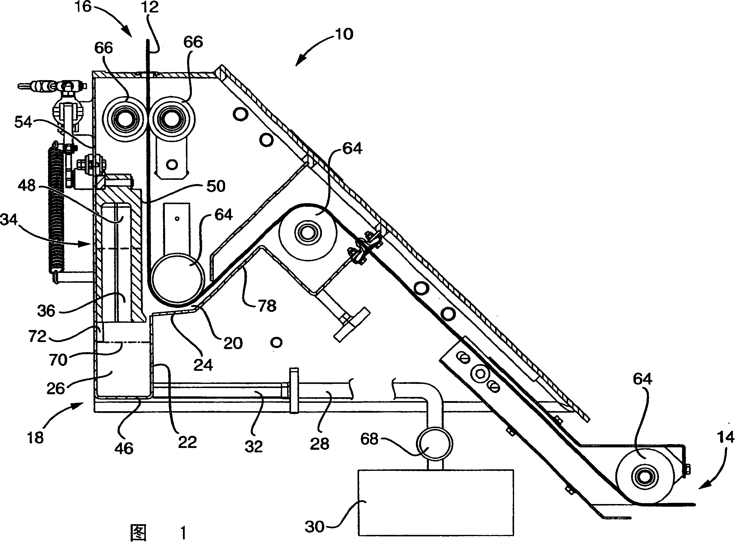
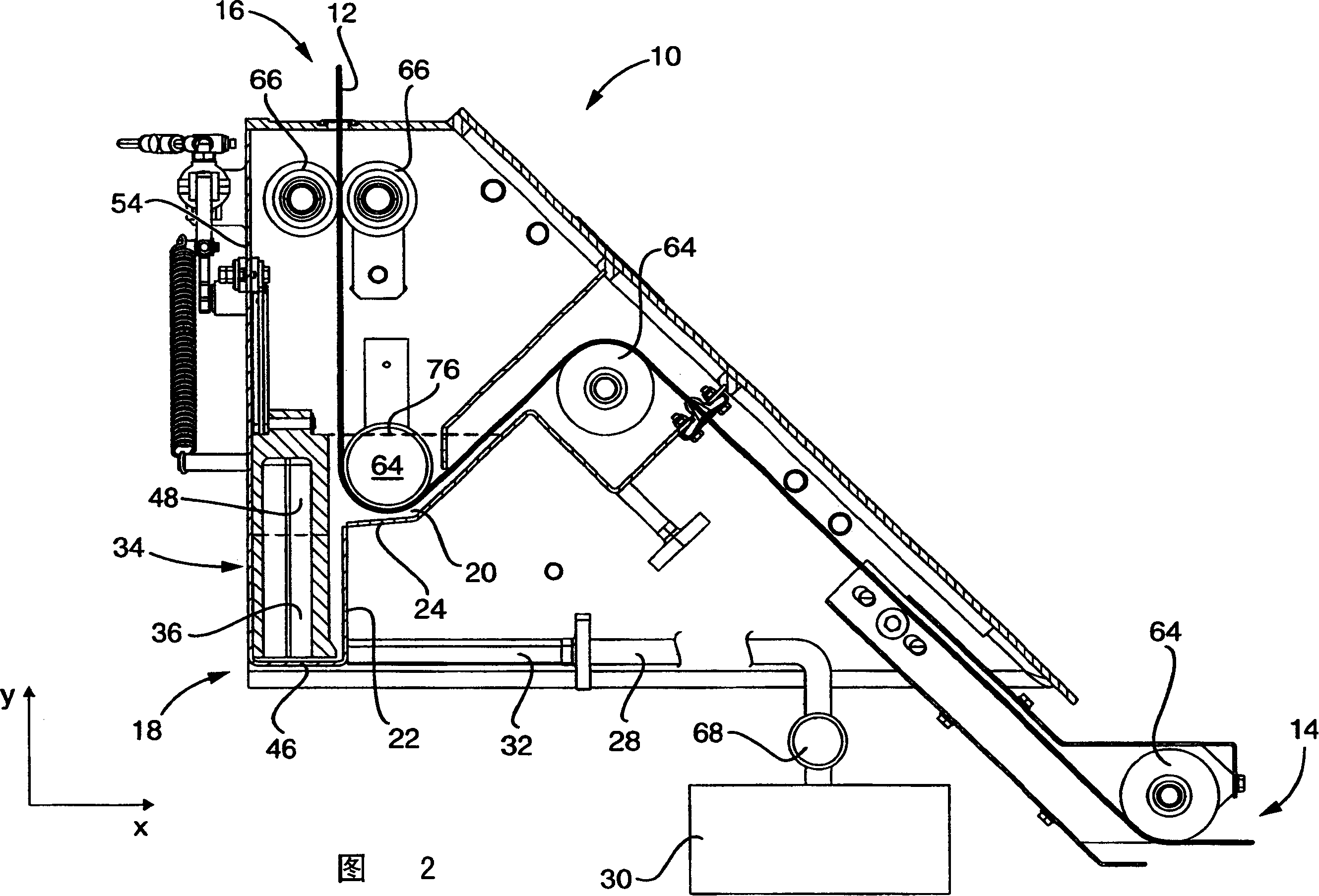
[0037] In Figures 1, 2 and 3 a sterilization device 10 is shown, through which a roll 12 of packaging material (shown only in Figures 1 and 2) passes, as described at the outset, before the tube is formed, filled and transversely sealed. to be sterilized. A roll 12 from a roll of packaging material (not shown) enters the apparatus 10 at an inlet 14 and exits the apparatus at an outlet 16 to enter a dryer (not shown).

[0038] Apparatus 10 includes a lower surge tank 18 and an upper bath 20 . The upper edge of the side wall 22 of the surge tank 18 is connected to the left edge of the bottom wall 24 of the bath 20, forming a direct transition between the surge tank and the bath. The bottom wall 24 of the bath 20 is not disposed perpendicular to the side wall 22 of the bath, but slopes gradually downward to the side wall 22 for reasons that will become apparent from the ensuing description. The interior 26 of the surge tank is substantially cuboid in shape. An inlet pipe 28 co...


PUM


Abstract

Packing material roll sterilizing apparatus and method is provided. The apparatus includes one bath for the rolled material to pass through and one sterilizing fluid conveying system from the source to the bath. The apparatus features that the conveying system includes one movable volume regulating element for regulating the sterilizing fluid from the source to the buffering tank and the sterilizing fluid from the buffering tank to the bath. The volume regulating element has at least one part set inside the buffering tank and acting on the sterilizing fluid inside the buffering tank, so that the volume of the sterilizing fluid inside the bath is the function of the position of the volume regulating element inside the buffering tank.

Description

technical field [0001] The present invention relates to an apparatus for sterilizing rolls of packaging material comprising a bath through which the rolls are to pass and a transfer system for delivering a sterilizing fluid from a sterilizing fluid supply to the bath. The invention also relates to a method for sterilizing a roll of packaging material comprising conveying a sterilizing fluid from a sterilizing fluid supply to a bath and passing the roll through the bath. Background technique [0002] In packaging technology, packages have long been used for packaging and transporting beverages, such as milk, fruit juices and other pourable products. Most of these packages are made of laminated packaging material comprising a core layer such as paper or cardboard, and a liquid-tight seal of thermoplastic material disposed at least on the side of the core layer forming the inside of the package. outer cladding. Sometimes the material also includes a gas barrier layer, for exa...

Claims


Application Information

Patent Timeline
Patent Type & Authority Applications(China)
IPC IPC(8): B65B55/10A61L2/18A61L101/22B65B
Inventor M·斯文勒
Owner TETRA LAVAL HLDG & FINANCE SA
Why Eureka
Try Eureka