
Wafer gluing system used for lithography machine
A technology for wafers and lithography machines, which is applied in the fields of photoplate-making process coating equipment, electrical components, semiconductor/solid-state device manufacturing, etc. It can solve problems such as limitations and low suction cup levelness, and achieve increased rigidity and adjustment efficiency. and regulation accuracy, avoiding the effect of movement
- Summary
- Abstract
- Description
- Claims
- Application Information
AI Technical Summary
Problems solved by technology
Method used
Image

Examples
Embodiment approach
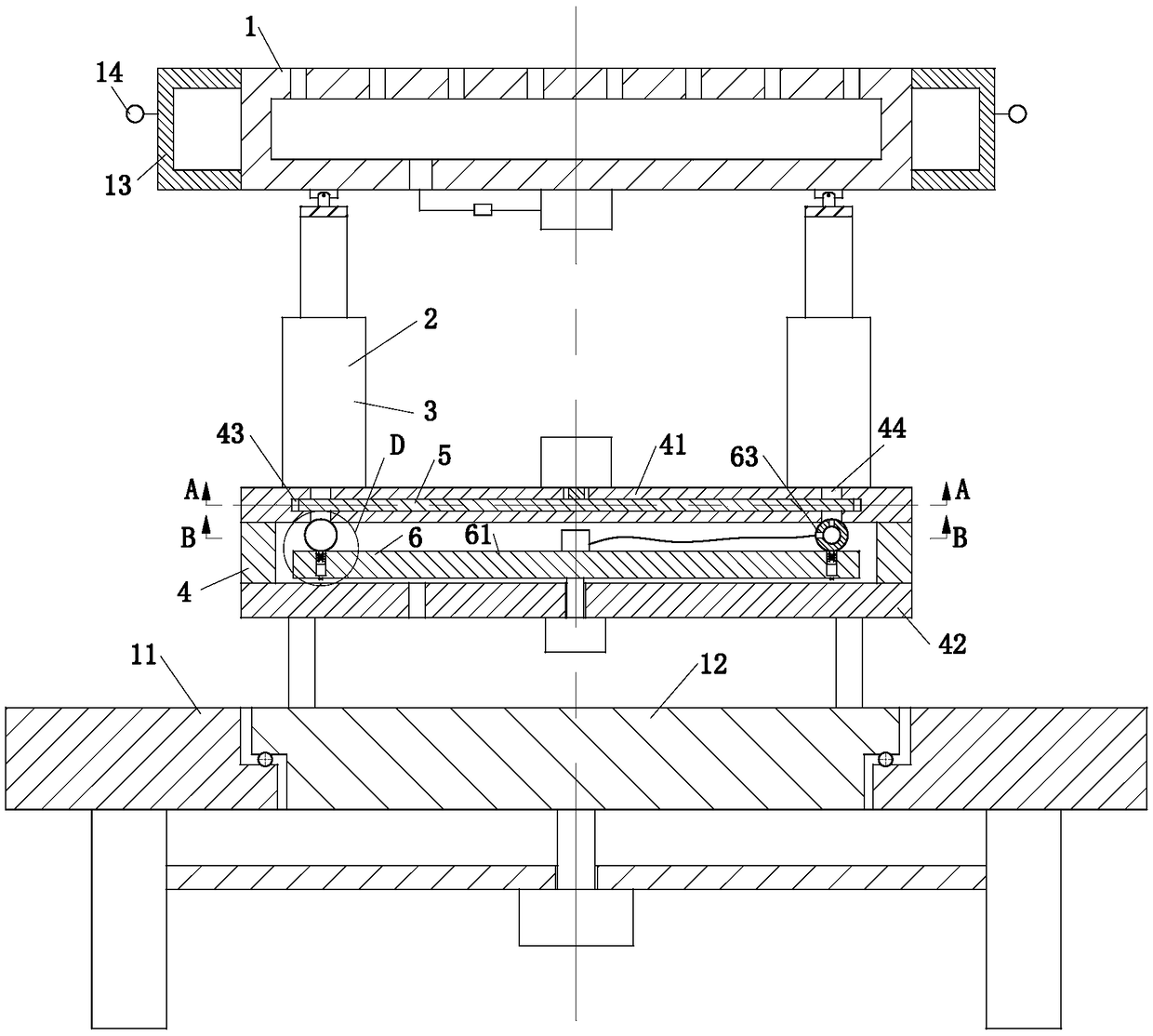
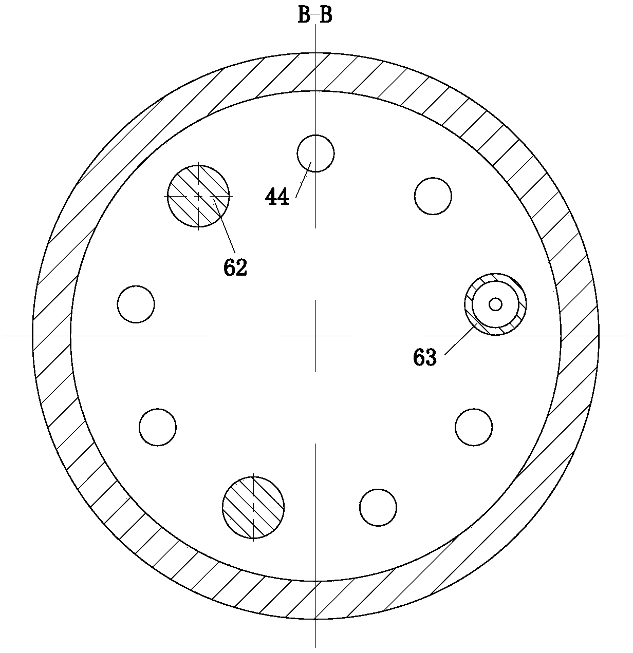
[0026] As an embodiment of the present invention, the air supply unit 6 includes a rotating disk 61, a spherical stopper 62 and a spherical air supply block 63; the rotating disk 61 is fixedly connected to the rotating shaft of the motor, and the bottom surface of the rotating disk 61 is provided with There is an electromagnet 64, and the top surface of the rotating disk 61 is provided with three No. 1 slots, and the three No. 1 slots are evenly distributed in a circular array; the spherical stopper 62 is installed in the No. 1 slot by means of a movable rod 65. The outer layer of the movable rod 65 is covered with a spring, and the bottom end of the movable rod 65 is provided with a magnet, and the magnet is used to cooperate with the electromagnet 64; the installation method of the spherical air supply block 63 and the spherical stopper 62 is consistent; The number of the spherical stopper 62 is two, and the number of the spherical air supply block 63 is one. The motor drive...
PUM
 Abstract
Description
Claims
Application Information