
Lighting device, backlight device, and liquid crystal display device

A lighting device and backlight device technology, applied in optics, static indicators, nonlinear optics, etc., can solve problems such as difficult uniformity of liquid crystal panels and inability to intersect uniformly

Inactive Publication Date: 2006-09-13
SHARP KK
View PDF1 Cites 6 Cited by
  • Summary
  • Abstract
  • Description
  • Claims
  • Application Information

AI Technical Summary

Problems solved by technology

Therefore, since the emitting direction of the light of the LED becomes the direction of the liquid crystal panel, and the combination of the fluorescent tube as the linear light source and the LED as the point light source, it is difficult to make the light transmitted through the liquid crystal panel uniform over the entire surface.
That is, there is a problem that the light emitted from the LED and the light emitted from the fluorescent tube do not intersect uniformly over the entire surface, and it is difficult to emit light that makes the light transmitted through the liquid crystal panel uniform over the entire surface.

Method used


Image

  • Lighting device, backlight device, and liquid crystal display device
  • Lighting device, backlight device, and liquid crystal display device
  • Lighting device, backlight device, and liquid crystal display device

Examples


Embodiment Construction

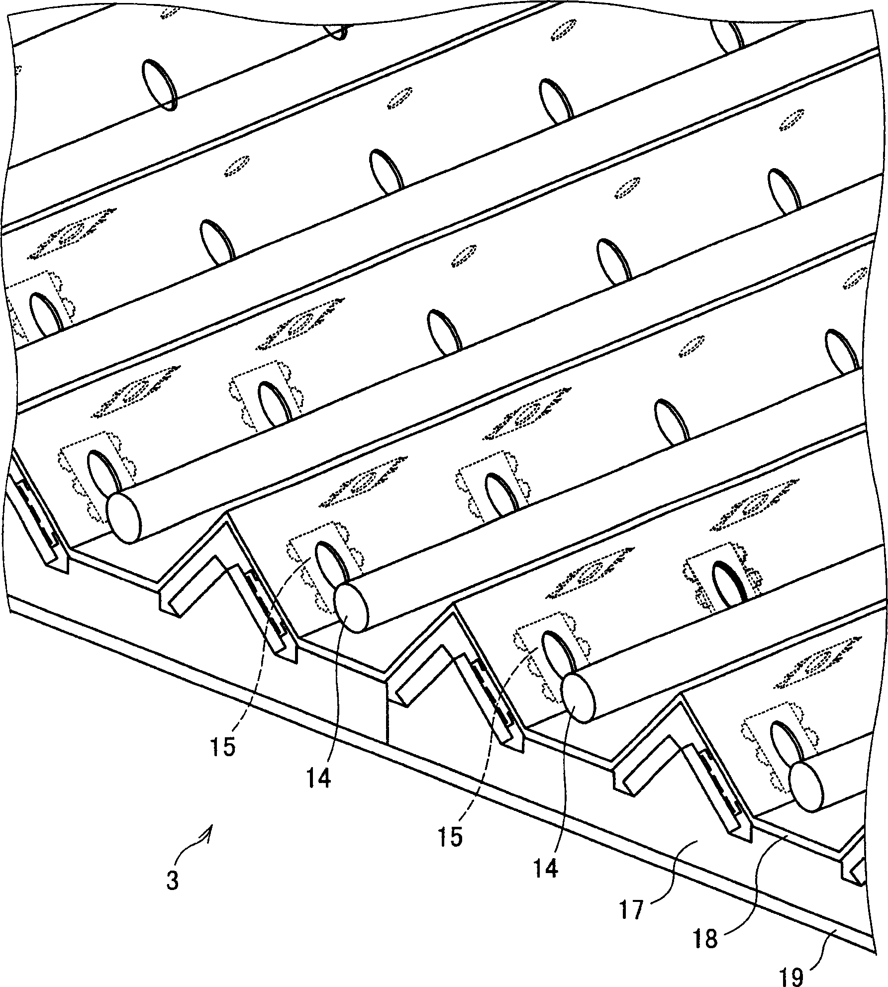
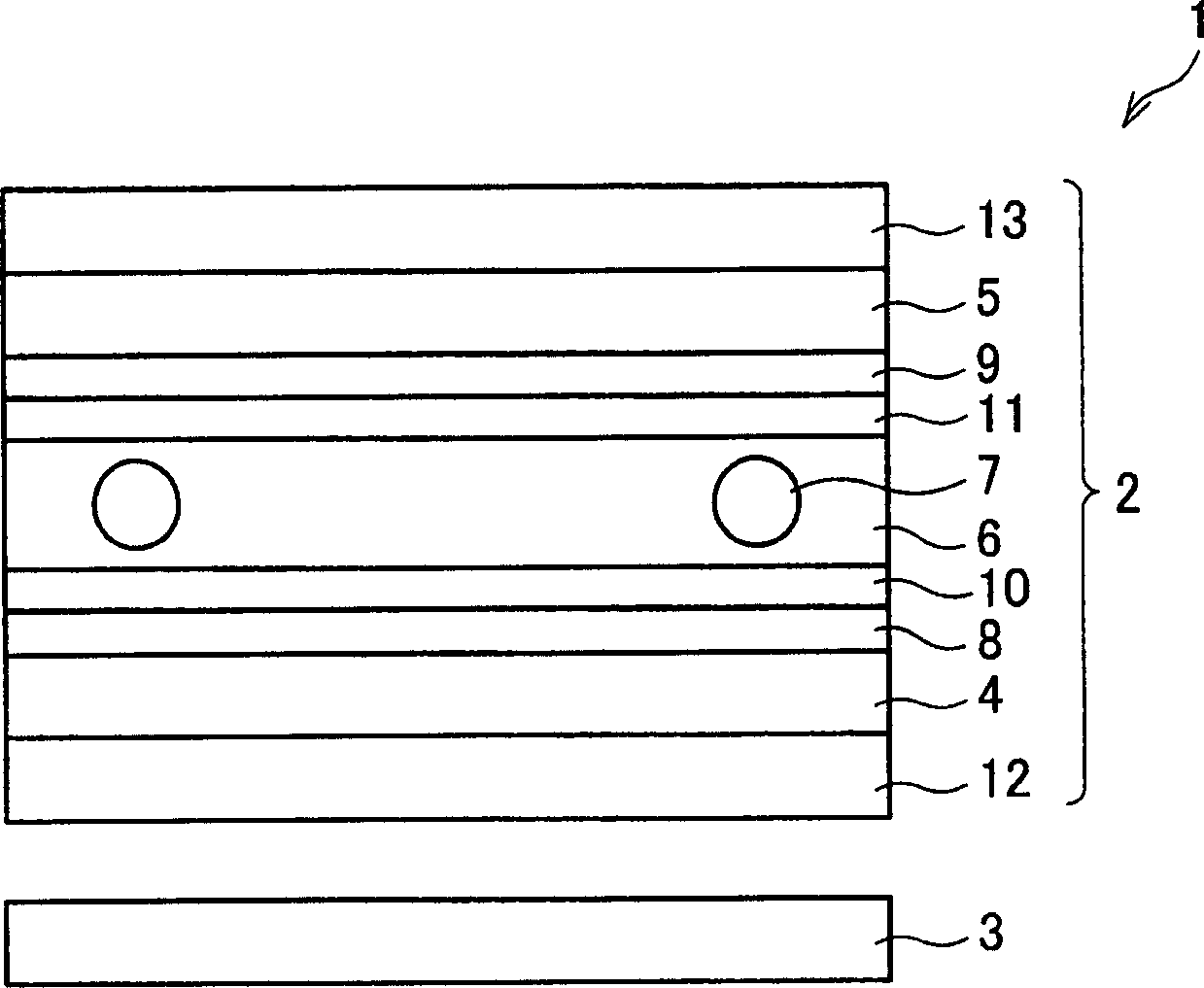
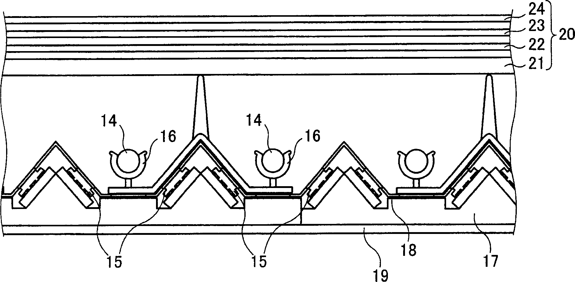
[0036] Below, refer to Figure 1 to Figure 8An example of the present invention will be described. figure 2 It is a cross-sectional view showing a schematic configuration of the liquid crystal display device 1 of this embodiment. Such as figure 2 As shown, a liquid crystal display device 1 has a liquid crystal cell 2 and a backlight unit (illumination device) 3 .

[0037] The liquid crystal cell 2 is a so-called liquid crystal panel having a liquid crystal layer 6 filled with liquid crystal molecules between two glass substrates 4 and 5 . For example, spherical or columnar spacers 7 are arranged between the two glass substrates 4 and 5 to maintain a certain distance between the glass substrates 4 and 5 . In addition, it has a structure in which the pixel electrode 8 is formed on one of the glass substrates 4 and 5 and the counter electrode 9 is formed on the other. In addition, alignment films 10 and 11 for aligning liquid crystal molecules in a certain direction are pro...


PUM


Abstract

The present invention is made to realize a lighting device capable of emitting uniform surface light having high luminance and a wide color reproduction range, and a backlight device a liquid crystal display device including the lighting device. Such a lighting device of the present invention includes: a GB lamp for emitting blue and green light; an RLED for emitting red light; and a light emitting section for irradiating, to outside, the light emitted from each of the GB lamp and the RLED. The light emitting section has an upper surface serving as a light emitting surface, and the GB lamp and the RLED are provided under the light emitting section. Further, the RLED is so provided as to emit the light in a direction that is not perpendicular to the light emitting surface.

Description

technical field [0001] The invention relates to an illuminating device and a liquid crystal display device with the illuminating device. More specifically, it relates to a lighting device using discharge tubes such as cold cathode tubes and LEDs (Light Emitting Diodes), and a liquid crystal display device including the lighting device. Background technique [0002] Conventionally, discharge tubes such as cold cathode tubes or LEDs (Light Emitting Diodes) have been mainly used as light sources for backlights of liquid crystal display devices. In the cold cathode tube, the excited mercury emits ultraviolet rays, and the ultraviolet rays come into contact with the phosphor coated on the inner wall of the glass tube, thereby emitting visible light. Usually, as this phosphor, by mixing R (red), G (green), and B (blue) colors, the emitted visible light becomes white. [0003] On the other hand, in an LED, holes and electrons generated by applying a voltage in the forward directi...

Claims


Application Information

Patent Timeline
Patent Type & Authority Applications(China)
IPC IPC(8): G02F1/13357G02F1/133G02F1/1335
CPCG02F1/133604G02F1/133603G02F1/133609
Inventor 星和法大谷直人青柳一郎关川宏志
Owner SHARP KK
Learn More