Unlock instant, AI-driven research and patent intelligence for your innovation.

Variable capacity device

A variable capacitance and resistance device technology, applied in capacitors, circuits, electrical components, etc., can solve problems that do not meet the needs, difficult to meet actual needs, complex masks, etc.

Inactive Publication Date: 2006-09-13
SUNPLUS TECH CO LTD
View PDF0 Cites 1 Cited by
  • Summary
  • Abstract
  • Description
  • Claims
  • Application Information

AI Technical Summary

Problems solved by technology

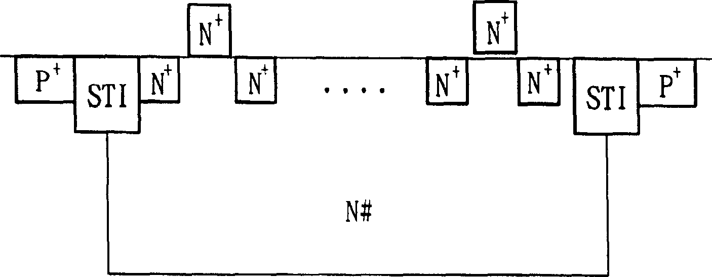
[0002] Traditional varactors can be completed using MOS process, such as figure 1 The MOS varactor shown has a Capacitance tuning ratio of less than 3 and requires a complex mask, which does not meet actual needs
figure 2 It is a diode varactor (Diode varactor), which is completed using a CMOS process, and its capacitance tuning rate is less than 2. Therefore, the capacitance can only be adjusted in a small range, and it is difficult to meet actual needs.
[0003] There are also digitally designed varactors, such as image 3 The digital varactor circuit shown, which consists of a capacitor C F 、C DO~N and switching transistors SO~N, where the switching transistor S O~N respectively control the capacitor C DO~N is connected in parallel to CF, therefore, by controlling the switching transistor S O~N Whether it is turned on or not, the number of capacitors connected in parallel can be changed, so the effect of adjusting the capacitance can be achieved, and by increasing the capacitor C DO~N The number can greatly increase its capacitance tuning rate. However, this capacitance change can only adjust the capacitance to a specific value, and cannot continuously adjust the capacitance.

Method used


Image

  • Variable capacity device
  • Variable capacity device
  • Variable capacity device

Examples


Embodiment Construction

[0014] For a preferred embodiment of the variable capacitance device of the present invention, please refer to Figure 4 The shown circuit diagram includes a capacitor circuit 41 and a feedback circuit 42, wherein the capacitor circuit 41 has a capacitor bank 411, a transistor 412, a current source 413 and a resistance device 414; and the feedback circuit 42 has a transistor 415 , a variable resistor 416 and a current source 417 , in this embodiment, the transistors 412 and 415 are MOS transistors.

[0015] In the aforementioned capacitor circuit 41 , the source S and the drain D of the transistor 412 are connected across the two ends of the capacitor bank 411 , and the aforementioned capacitor bank 411 is a capacitor 4111 or a plurality of capacitors 4111 connected in parallel. The aforementioned current source 413 is connected in series with the source S of the transistor 412 to provide a bias current to the transistor 412 so that the transistor 412 can operate in its workin...


PUM


Abstract

This invention relates to a variable condenser device including a condenser set and a condenser circuit of a first transistor bridge-jointing said condenser set, a first variable resistor and a second transistor, in which, said second transistor is coupled to said first transistor and serial to said first variable resistor for feeding back the output signal generated by applying the voltage on the condenser circuit to the first transistor to control the gain of the first transistor by adjusting the first variable resistor.

Description

technical field [0001] The invention relates to a variable capacitance device, in particular to a variable capacitance device which can continuously adjust the capacitance in a wide range. Background technique [0002] Traditional varactors can be completed using MOS process, such as figure 1 The MOS varactor shown has a capacitance tuning ratio of less than 3 and requires a complex mask, which does not meet actual needs. figure 2 It is a diode varactor (Diode varactor) made by CMOS process, and its capacitance tuning ratio is less than 2. Therefore, the capacitance can only be adjusted in a small range, and it is difficult to meet the actual needs. [0003] There are also digitally designed varactors, such as image 3 The digital varactor circuit shown, which consists of a capacitor C F 、C DO~N and switching transistors SO~N, where the switching transistor S O~N respectively control the capacitor C DO~N is connected in parallel to CF, therefore, by controlling the sw...

Claims


Application Information

Patent Timeline
IPC IPC(8): H03H11/00H03H11/02H01G17/00H01L29/00
Inventor 钟元鸿
Owner SUNPLUS TECH CO LTD