High density flash memory with high speed cache data interface

A data interface and data storage technology, which is applied in the fields of electrical digital data processing, information storage, static memory, etc., and can solve problems such as limited storage density

Inactive Publication Date: 2006-09-13
INFINEON TECH AG
View PDF0 Cites 12 Cited by
  • Summary
  • Abstract
  • Description
  • Claims
  • Application Information

AI Technical Summary

Problems solved by technology

However, current FeRAM technology only allows limited storage densities, less than 1Mbit (although it is envisaged that densities in the 32Mbit range will be commercialized at reasonable cost)

Method used


Image

  • High density flash memory with high speed cache data interface

Examples


Embodiment Construction

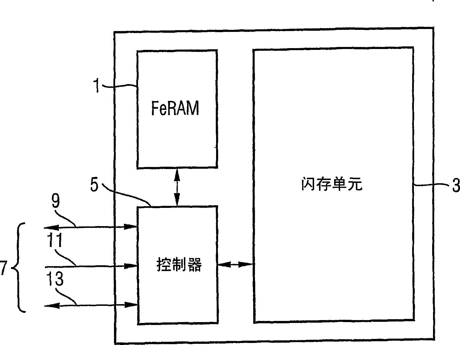
[0009] Such as figure 1 As shown, the storage element as an embodiment of the present invention includes a FeRAM unit 1 , a flash memory unit 3 and a controller 5 . The FeRAM cell 1 has a smaller storage capacity than the flash memory cell 3 . Typically, the storage capacity of the FeRAM unit 1 is greater than 1Mbit, such as 4Mbit, and the storage capacity of the flash memory unit 3 is greater than 100Mbit, such as 128Mbit.

[0010] The element has an interface 7 (implemented by a plurality of pins) comprising: a data I / O interface 9 for receiving data to be stored in the storage element and sending data retrieved from the storage element; an address interface 11, For receiving the signal representing the address of the data to be stored; and the control signal interface 13, for receiving the control signal, the control signal includes: "write signal", indicating that the data received by the data I / O interface 9 will be stored in the interface 11 In the address represented ...


PUM


Abstract

A data storage device comprises a controller, a FeRAM memory unit, and a flash memory unit having a much higher data storage capacity than the FeRAM memory unit. Initially, when data is received by the data storage device, the controller stores it in the FeRAM memory unit. This can be done very quickly, since FeRAM devices have a high write rate. Subsequently, the controller transfers the data to the flash memory unit. Thus, the data storage device combines the high storage rate ability of FeRAM devices and the high storage capacity of flash memory devices.

Description

technical field [0001] The present invention relates to a data storage element providing non-volatile data storage. Background technique [0002] Flash memory (also known as FEPROM, "Fast Erasable Read Only Memory") is a well-established technology. It is defined as a type of EPROM (Erasable Programmable Read-Only Memory) in which erasing can be easily done in a memory block or in an entire memory chip, and for chips installed in a computer system, erasing can be done . Currently available flash memory chips provide very high storage densities (eg, 512Mbit, or higher). Reading data from this type of memory is quite fast, however writing to flash memory is a slower operation due to the storage principle of flash memory. Typically, data write operations are on the order of milliseconds or more. [0003] In contrast, the new technology of FeRAM (Ferroelectric Random Access Memory) provides non-volatile RAM with very fast write performance, with write memory times in the ran...

Claims


Application Information

Patent Timeline
Patent Type & Authority Applications(China)
IPC IPC(8): G11C16/10G11C11/00G06F12/08G11C8/12
CPCG11C16/10G11C8/12G06F2212/2022G06F2212/2024G11C2207/2245G06F12/0893
Inventor 托马斯·勒尔迈克尔·雅各布诺伯特·雷姆汉斯-奥利弗·约瑟夫
Owner INFINEON TECH AG
Why Eureka
Try Eureka