Supercharge Your Innovation With Domain-Expert AI Agents!

Mechanical reduction gear and rim motor including the same

A gear reduction and gear technology, which is applied in the field of gear reduction mechanisms, can solve problems such as large volume, deflection and deformation of fixed columns, and bulky and complicated design.

Inactive Publication Date: 2006-09-20
李宝玲
View PDF0 Cites 4 Cited by
  • Summary
  • Abstract
  • Description
  • Claims
  • Application Information

AI Technical Summary

Problems solved by technology

[0013] When the system is at high torque output, these shear stresses will be amplified, which will easily cause the fixed column to bend and deform. The magnitude of the shear force will change repeatedly, making it easier to deform
And even a small deformation will increase the vibration and noise of the gear, and may even cause the gear to be stuck
[0014] In addition, this kind of design is extremely bulky and complicated, and the entire reduction mechanism needs to occupy more space to arrange gears of different sizes side by side. In order to achieve a high reduction ratio, the volume of the reduction mechanism may even be larger than the volume of the motor itself.

Method used


Image

  • Mechanical reduction gear and rim motor including the same
  • Mechanical reduction gear and rim motor including the same
  • Mechanical reduction gear and rim motor including the same

Examples


Embodiment Construction

[0048] The present invention will be described in further detail below in conjunction with the accompanying drawings.

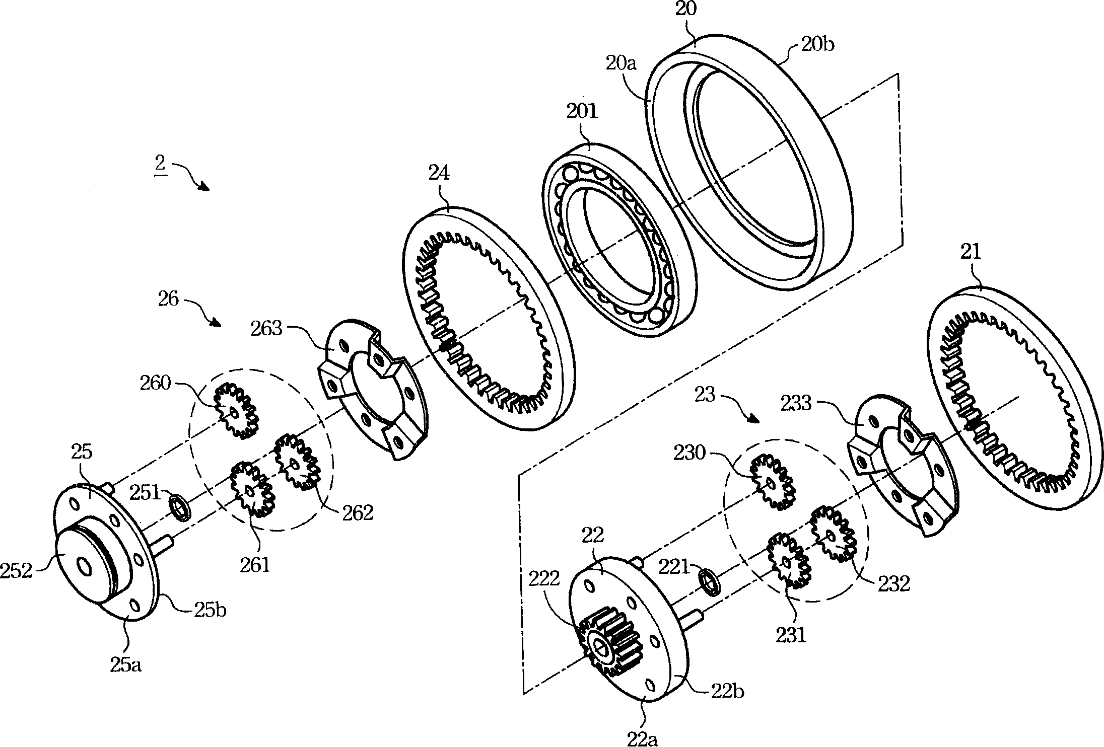
[0049] Such as image 3 Shown is an exploded view of a preferred embodiment of the gear reduction mechanism of the present invention.

[0050] As shown in the figure, the gear reduction mechanism 2 in this embodiment includes a housing frame 20, a second ring gear 21, a second bracket 22, a first gear assembly 23, a third ring gear 24, and a third bracket 25. The second gear assembly 26.

[0051] The shell frame 20 has a ring-shaped structure, and a first bearing 201 is arranged at the center thereof.

[0052] The second ring gear 21 is installed on one side 20b of the frame 20 . The tooth shape of its inner edge is positive tooth shape in this embodiment.

[0053] The second bracket 22 is disc-shaped, sleeved in the first bearing 201 , and can rotate in the first bearing 201 . In practice, various components (such as gears, ring gears, shafts of rotatin...


PUM


Abstract

The present invention relates to a gear reduction mechanism. It includes at least one ring gear, second bracket, first gear assembly, third bracket and second gear assembly, in which the centre of said second bracket possesses first convex shaft. Said first gear assembly is positioned at another side of said second bracket, meshed with ring gear and coupled with the output shaft of rotation power source; the second gear assembly is positioned at another side of the third bracket, meshed with ring gear and coupled with first convex shaft of second bracket. When the rotation power source is worked, the first gear assembly is rotated and can be used for driving first convex shaft of second bracket and making it be rotated to make the second gear assembly the rotated so as to make the between of ring gear and third bracket produce relative movement to output power.

Description

technical field [0001] The invention relates to a gear reduction mechanism, in particular to a gear reduction mechanism capable of multi-stage reduction to increase output torque and a rim motor with the gear reduction mechanism. Background technique [0002] In today's industrial society, whether it is people's daily life or the production and manufacture of various products, mechanical devices have already become an indispensable part. Among them, some mechanical devices that use motors or engines as power sources and require high torque output, such as cutting machines, punching machines, transportation systems, etc., all use reduction mechanisms to increase the torque output of the motor. [0003] In various reduction mechanisms, planetary gear trains are often used to increase the output torque of the motor, such as figure 1 Shown is a schematic diagram of the planetary gear train 10 . It mainly includes a sun gear 101 , a planetary gear set 102 , a first carrier 103 ...

Claims


Application Information

Patent Timeline
IPC IPC(8): F16H1/32H02K7/10
Inventor 李宝玲
Owner 李宝玲
Features
  • R&D
  • Intellectual Property
  • Life Sciences
  • Materials
  • Tech Scout
  • Unparalleled Data Quality
  • Higher Quality Content
  • 60% Fewer Hallucinations
Learn More