Non-contact reading sensor of mechanical character wheel counter and its design method

A mechanical character wheel and counter technology, applied in the direction of counting mechanisms/items, instruments, etc., can solve the problems of no electronic digital output equipment, etc., and achieve the effects of high accuracy, long life and convenient use

Inactive Publication Date: 2006-09-20
张安戈
View PDF0 Cites 18 Cited by
  • Summary
  • Abstract
  • Description
  • Claims
  • Application Information

AI Technical Summary

Problems solved by technology

However, due to the development of technology, many places require that the measuring instrument can output the measurement results in an electronic digital way for remote transmission or directly to the computer for data processing. However, due to the lack of corresponding electronic digital output equipment

Method used


Image

  • Non-contact reading sensor of mechanical character wheel counter and its design method
  • Non-contact reading sensor of mechanical character wheel counter and its design method
  • Non-contact reading sensor of mechanical character wheel counter and its design method

Examples


Embodiment 1

[0024] Applied on 8 phototransistor sensors.

[0025] Design of support and circuit board:

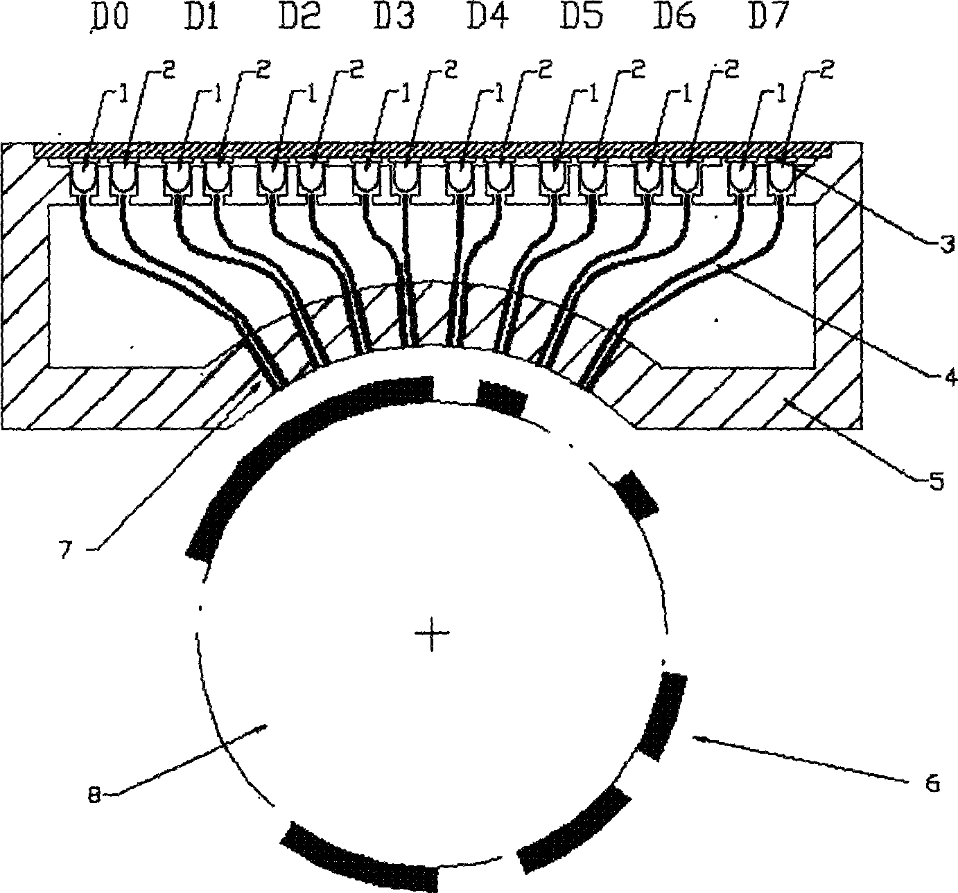
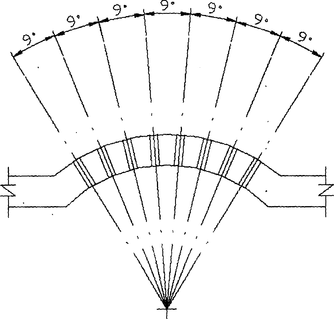
[0026] (1) Determine the number of phototransistors corresponding to each character wheel N=8 (see attached figure 1 );

[0027] (2) Calculate the angle between two adjacent fiber fixing holes:

[0028] α=360÷[(8-3)×8]=9 degrees;

[0029] (3) The number of fiber fixing holes is 8, and the interval angle is 9 degrees (see attached figure 2 );

[0030] According to the above method, the bracket (5) and the fiber positioning hole (7) on the bracket (5) are designed, and the circuit board (3) is equipped with 8 phototransistors (see attached figure 1 ).

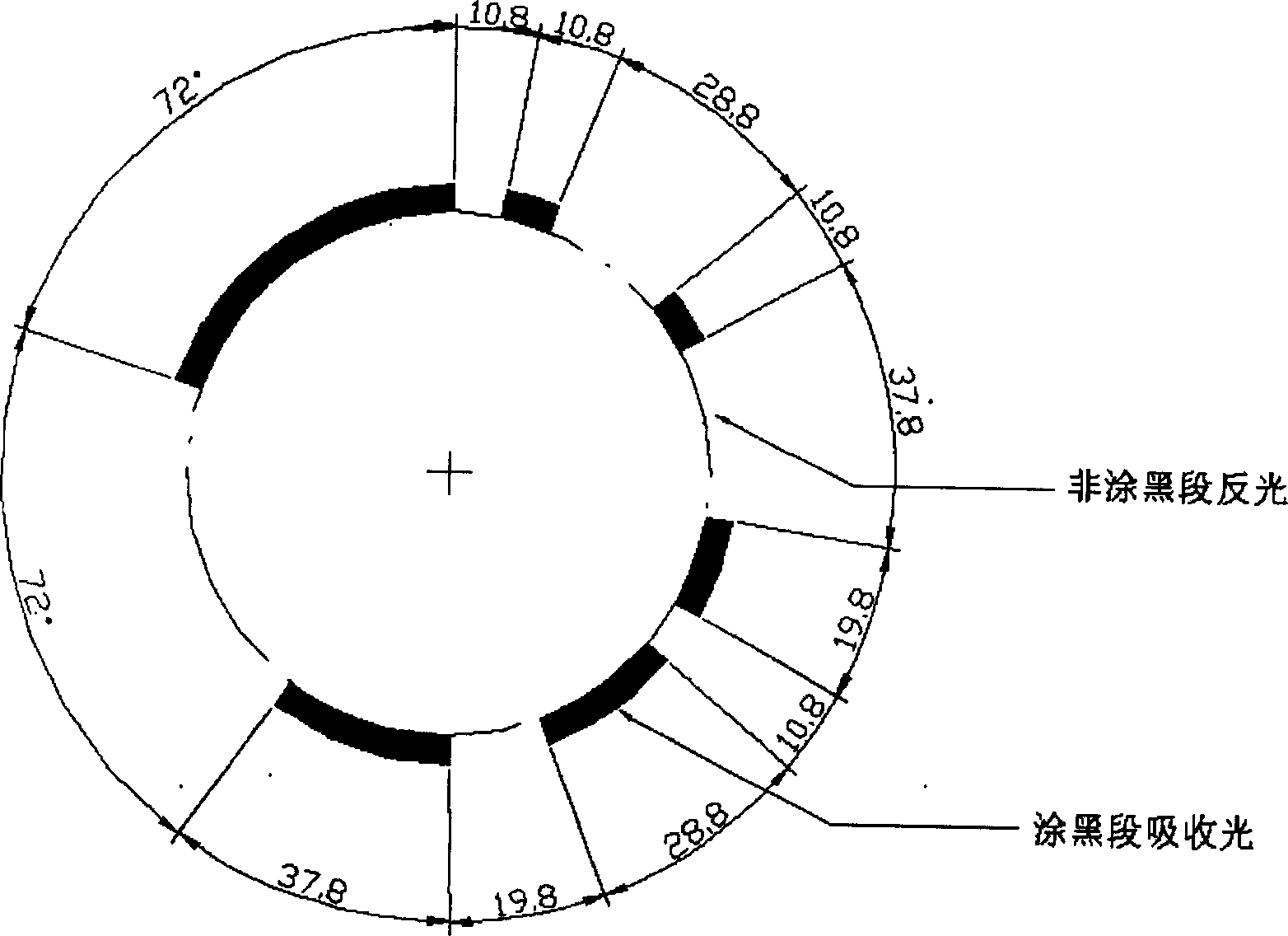
[0031] Design of reflective strips:

[0032] (1) The length of the reflective section and the non-reflective section is measured by the angle between the center of the character wheel;

[0033] (2) Calculation of the length of each section:

[0034] α MK =360×(K+1 / M)÷[(N-3)×N]

[0035] α 0 =360÷(N-3)

[0036] When N=8; M=5; K=1, 2, 3, 4, 5...

Embodiment 2

[0060] It is applied to 7 phototransistor sensors.

[0061] Design of bracket and circuit board:

[0062] (1) Determine the number of phototransistors corresponding to each character wheel N=7 (see attached Figure 4 );

[0063] (2) Calculate the angle between two adjacent fiber fixing holes:

[0064] α=360÷[(7-3)×7]=360÷28=12.9 degrees;

[0065] (3) The number of fiber fixing holes is 7, and the interval angle is 12.9 degrees (see attached Figure 5 );

[0066] According to the above method, the fiber positioning holes (7) on the bracket (5) and the outlet bracket (5) and the circuit board (3) are equipped with 7 phototransistors (see attached Figure 4 ).

[0067] Design of reflective strips:

[0068] (1) The length of the reflective section and the non-reflective section is measured by the angle between the center of the character wheel;

[0069] (2) Calculation of the length of each section:

[0070] α MK =360×(K-1 / M)÷[(N-3)×N]

[0071] α 0 =360÷(N-3)

[0072] When N=7; M=3; K...


PUM


Abstract

The invention provides a mechanical wheel counter noncontact reading sensor and the design method thereof, using the light reflection principle to convert optical signal into electric signal code data so as to implement a function of noncontact mode reading of counter wheel indicated figures, where photoelectric triode, photoelectric diode and signal processing circuit are arranged on a circuit board on the upper part of a bracket, the lower part of the bracket is made with optical fiber fixing holes, the optical fiber is connected between the photoelectric triode, photoelectric diode and optical fiber fixing holes as a light path, the lower part of the bracket is provided with a wheel pasted with light reflecting strip to read code data from the photoelectric triode, and a MCU looks up a wheel figure-code data contrast table to convert the code data into counter wheel indicated figures, which are outputted through serial socket. The invention accurately calculates included angles between the optical fiber fixing holes and geometric parameters of the light reflecting strip and can implement remote data transmission.

Description

Technical field: [0001] The invention relates to the technical field of data recognition in measurement technology, and to be precise, it is a non-contact reading sensor of a mechanical word wheel counter and a design method of the sensor. Background technique: [0002] Mechanical rotary counters are widely used in water meters, electric meters, gas meters, odometers and other accumulative measuring instruments. Due to their simple structure and reliable and stable operation, they have been an irreplaceable measurement method for a considerable period of history. . However, due to the development of technology, many places require the measurement instrument to output the measurement results in an electronic digital way for remote transmission or directly to the computer for data processing, and this type of instrument has no corresponding electronic digital output equipment. Summary of the invention: [0003] The purpose of the present invention is to provide a mechanical charac...

Claims


Application Information

Patent Timeline
Patent Type & Authority Applications(China)
IPC IPC(8): G06M1/272
CPCG06M1/272
Inventor 张安戈
Owner 张安戈
Why Eureka
Try Eureka