Drive method for backlight module of LCD device and its circuit

A liquid crystal display and backlight module technology, applied in static indicators, light sources, electric light sources, etc., can solve the problems of complicated circuits, reduced product reliability, easy to generate high heat, etc., to achieve high conversion efficiency, uniform brightness, and difficult heat effect

Inactive Publication Date: 2006-09-20
余洪烈 +2
View PDF0 Cites 4 Cited by
  • Summary
  • Abstract
  • Description
  • Claims
  • Application Information

AI Technical Summary

Problems solved by technology

[0006] 1. Low power conversion efficiency: the conversion efficiency of the entire drive circuit is only about 70% because the AC power is first converted into a low-voltage DC power source by the switching power supply unit, and then converted into a high-voltage and high-frequency AC power source by a transformer.
[0007] 2. Easy to generate high heat: Since the power supply is not completely and effectively converted, about 30% of the energy of the power supply will be converted into heat energy, making the backlight module prone to heat
If this backlight module is applied to the liquid crystal display panel, the heat generated will accelerate the deterioration of the liquid crystal, shorten the service life of the liquid crystal display panel, relatively increase the failure rate of the entire liquid crystal display, and reduce the reliability of the product
[0008] 3. Uneven brightness: such as Figure 8 and Figure 9 As shown, since the cold cathode lamp tube 71 is connected to both ends of the secondary side of the step-up transformer 70, one end of the secondary side is connected to the high voltage, and the other end is connected to the ground terminal, so a high-voltage high-frequency power input lamp tube At 71 o'clock, the lamp tube 71 is driven to light up
[0010] 4. Applied to driving multiple lamp tubes, there are disadvantages such as complex circuits, more components, and higher costs: limited by the connection relationship between the lamp tube 71 and the step-up transformer 70, such as Figure 10 As shown, if the front driving circuit is to be connected with a plurality of lamp tubes 71, then a plurality of step-up transformers 70 need to be connected in parallel.
[0011] From the previous explanations, it can be seen that there are still quite a few shortcomings to be overcome in the application of the current lamp drive circuit to drive multiple lamps.

Method used


Image

  • Drive method for backlight module of LCD device and its circuit
  • Drive method for backlight module of LCD device and its circuit
  • Drive method for backlight module of LCD device and its circuit

Examples


Embodiment Construction

[0047] In order to further understand the structural features and other purposes of the present invention, the detailed description is as follows in conjunction with the accompanying drawings:

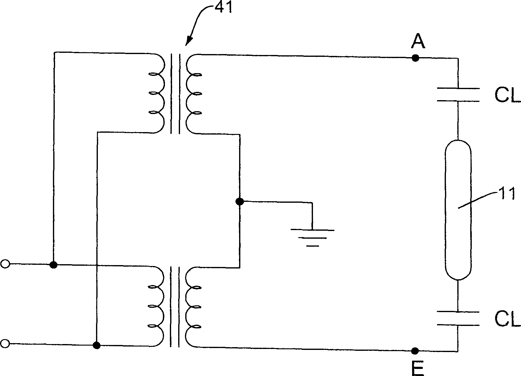
[0048] The invention is a driving circuit for driving a lamp tube to produce uniform luminance, and is mainly applied to a liquid crystal display. see first figure 1 As shown, the method of driving the lamp tube of the present invention is to connect the two ends of the lamp tube 11 to the high-frequency high-voltage power supply with a common ground, and to make the tube current more uniform and stable, a capacitor CL is connected in series at the two ends of the lamp tube 11 respectively. When connecting multiple groups of lamp tubes 11, connect a capacitor CL in series at both ends of each lamp tube 11, then connect the plurality of lamp tubes 11 in parallel, and connect the two nodes connected in parallel to two high-frequency high-voltage The power supply makes the two ends of e...


PUM


Abstract

The invention comprises: after a plurality of luminous tubes are connected in parallel, and then connecting two nodes in parallel to the two ends at secondary side of the voltage increase center tap transformer; the center tap at the secondary side is connected to the ground end; the primary side of the voltage increase transformer is connected to a high frequency signal and is driven by the high frequency signal; thereby, both ends of the luminous tubes will get high voltage and identical current making the luminous tubes generate even light.

Description

technical field [0001] The invention relates to a driving method and a circuit of a backlight module of a liquid crystal display, in particular to a driving method and a circuit for driving the backlight module to produce uniform luminance. Background technique [0002] The liquid crystal display panel itself does not have self-luminous characteristics, so it needs to be equipped with a backlight module to provide a display light source. Among them, a large-sized liquid crystal display panel requires a uniform and high-brightness backlight module, so most of them use cold cathode lamps as the light source. [0003] At present, there are not a few manufacturers at home and abroad that develop driving circuits for cold cathode lamps, and the functional requirements of the driving circuits designed by each manufacturer are different. As the size of the liquid crystal display panel increases, the number of lamp tubes also increases, so that the early lamp drive circuits are no l...

Claims


Application Information

Patent Timeline
Patent Type & Authority Applications(China)
IPC IPC(8): H05B41/24G02F1/133
Inventor 余洪烈洪棕堡罗家村
Owner 余洪烈
Why Eureka
Try Eureka