Vibration chain type feeding screw rod kneading extruder

An extrusion device and screw technology, which is applied in the field of vibrating chain feeding screw kneading and extrusion devices, can solve the problems of low accumulation density of fly ash, pulsating feeding of materials, unstable fly ash, etc., and achieve stable and reliable working performance. The effect of stable feeding amount and simple structure

Inactive Publication Date: 2006-09-27
天津市石化通用机械研究所有限公司
View PDF0 Cites 3 Cited by
  • Summary
  • Abstract
  • Description
  • Claims
  • Application Information

AI Technical Summary

Problems solved by technology

[0002] At present, the screw extruder mainly relies on the screw and cylinder liner in the kneading and extrusion chamber for uniform mixing of powder and liquid, chemical reaction and granulation, extrusion of round rods or homogenization of materials with uneven particle size after cutting. The mutual movement of the screw extruder of the prior art has the following disadvantages: due to the small bulk density of fly ash, for example, the bulk density of fly ash is about 0.6, and the main material inlet of the screw kneading extruder shrinks relative to the silo. The diameter of the screw extruder is very large, and it is easy to bulge during work. The fly ash cannot enter the kneading chamber of the screw extruder stably to complete the work of conveying raw materials.
Some of the existing technologies use the mechanical vibration device of the silo, which is noisy, and the material still has a pulsating feeding phenomenon, and the mechanism is complicated and the cost is high; there are also pneumatic vibration or loosening methods, which not only need to increase the complete set of compressed air equipment, but also work still unstable

Method used


Image

  • Vibration chain type feeding screw rod kneading extruder
  • Vibration chain type feeding screw rod kneading extruder
  • Vibration chain type feeding screw rod kneading extruder

Examples


Embodiment 1

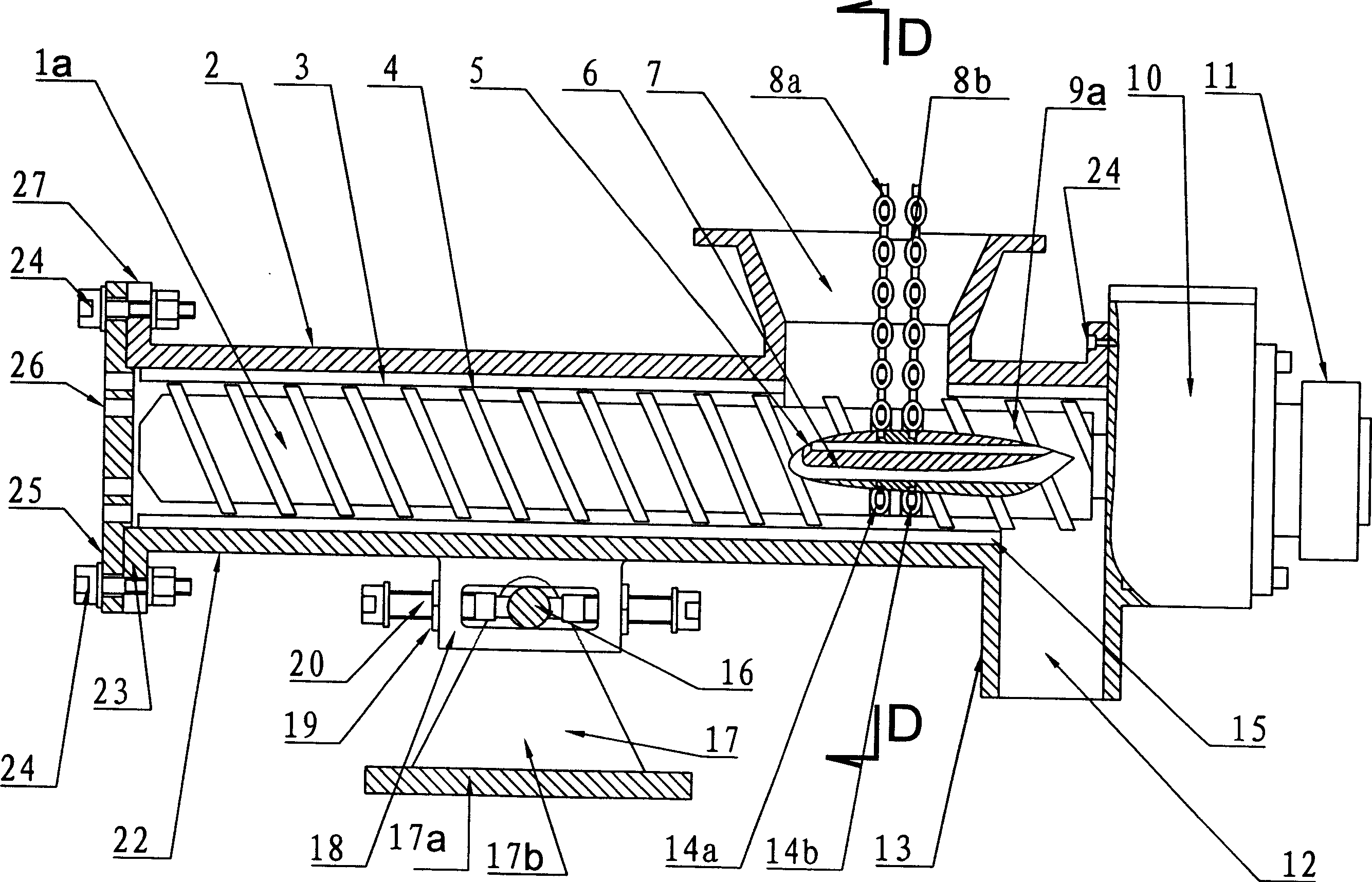
[0044] Vibrating chain feeding screw kneading extrusion device, refer to the attached figure 1 , figure 2 , two tangential screw structure diagrams; embodiment 4: refer to accompanying drawings 6, 7, Figure 8 , One side of the extruder adopts a hinged frame, and the pressure side of the reducer frame 52 on the other side of the extruder is provided with an elastic balance device.

[0045] The vibrating chain feeding screw kneading extrusion device includes a rotating mechanical drive mechanism, an extruder, a mixing bin 41, a frame 45 and a chain feeding device; the extruder includes a screw 1, a cylinder liner, a casing, and a main material The feed port 7, the kneading material discharge port, and the auxiliary material feed port 43, etc.; the main material feed port 7, the machine base and the laying material feed port 43 are arranged on the right side of the upper half cylinder liner 2, and the laying material feed port 43 It is a liquid pipeline; the screw rod is arra...

Embodiment 2

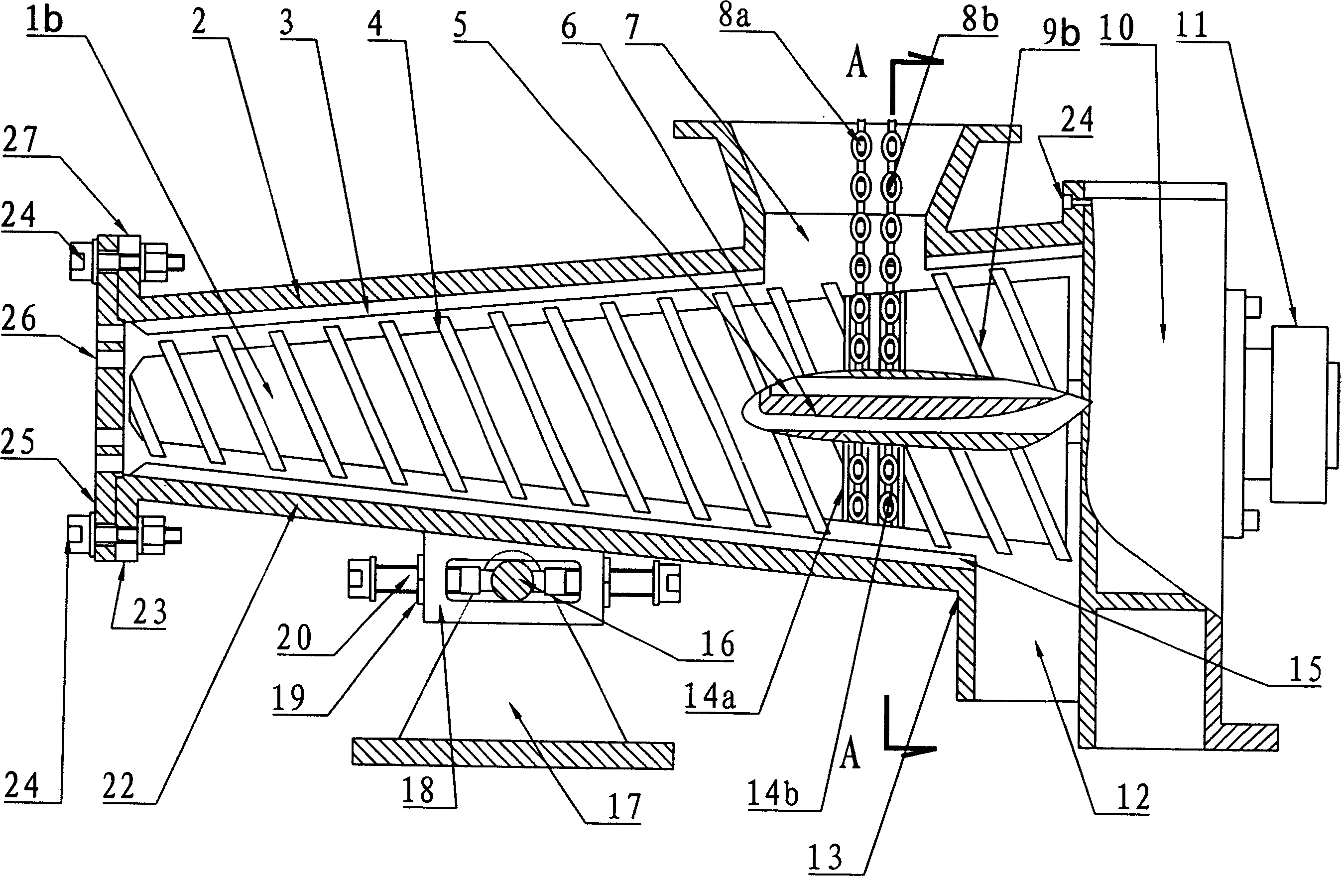
[0052] Vibrating chain feeding screw kneading extrusion device, refer to the attached image 3 , Figure 4 , a schematic diagram of the structure of a full-cone single-screw extruder; Figure 11 , the extruder is fixed on the frame, and the mixing bin adopts a structural schematic diagram of an elastic balance device.

[0053] The vibrating chain feeding screw kneading extrusion device includes a rotary mechanical drive mechanism, an extruder, a mixing bin 41, a frame 45 and a chain feeding mechanism basically the same as in Embodiment 1. The difference is:

[0054] exist Figure 11 Among them, the B technical scheme of the tensioning device is set between the base of the extruder and the frame, and the tensioning device (B technical scheme) is provided between the mixing bin and the frame. The tensioning device includes a flexible channel and Elastic balance device 47; Flexible channel 42 is set on the flange between the mixing bin discharge port and the main material feed ...

Embodiment 3

[0058] Vibrating chain feeding screw kneading extrusion device, refer to the attached Figure 5 Schematic diagram of the sectional structure of a single-screw extruder combined with semi-equal diameter and semi-conical shape; referring to accompanying drawings 9 and 10, the extruder is fixed on the frame, and the mixing chamber adopts a structural schematic diagram of an elastic balance device.

[0059] The vibrating chain feeding screw kneading extrusion device includes a rotary mechanical drive mechanism, an extruder, a mixing bin 41, a frame 45 and a chain feeding mechanism basically the same as in Embodiment 1. The difference is:

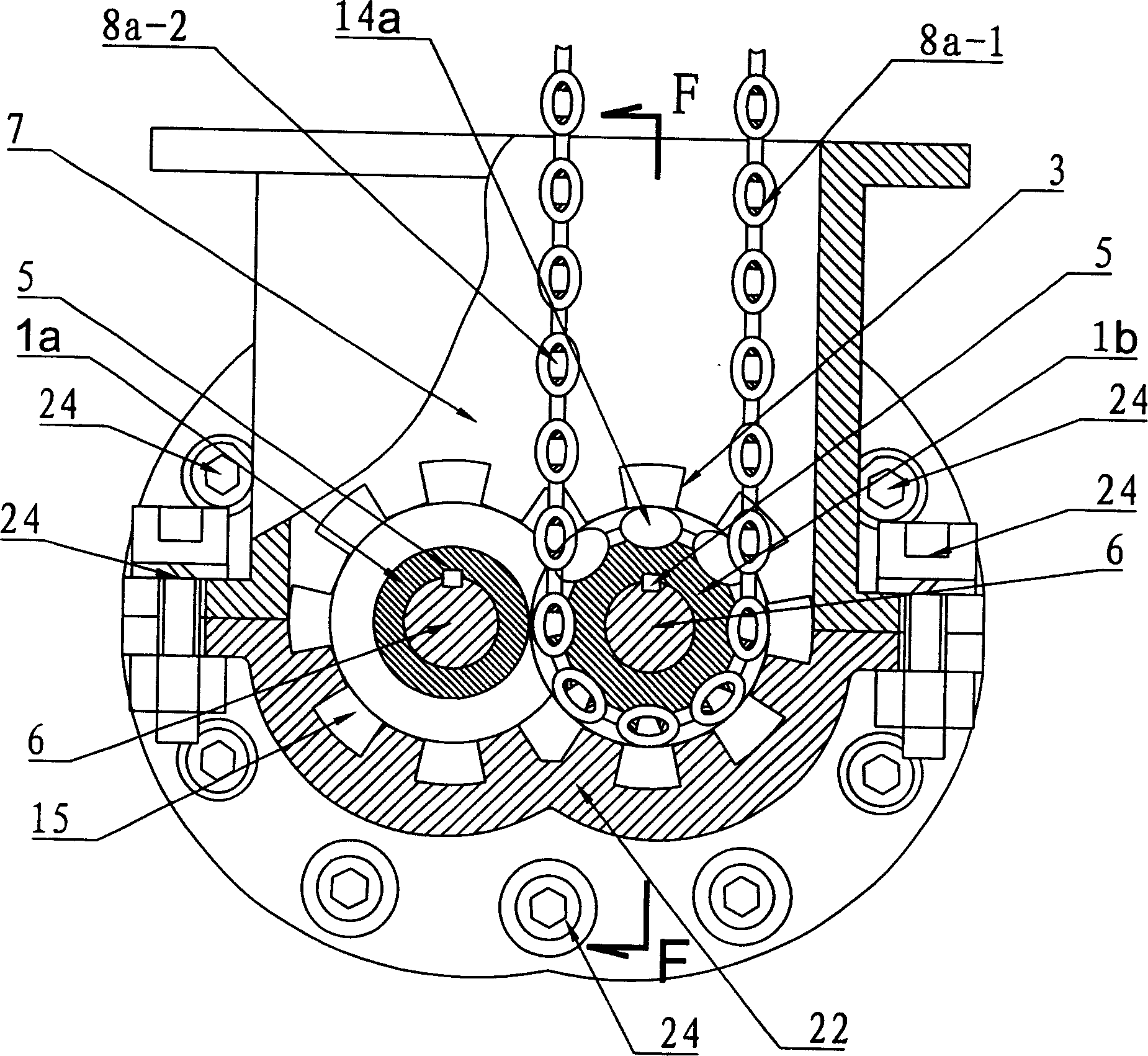
[0060] In Fig. 9, the rotation center of the first driven wheel 35a passed by the chain cables protruding from the two ends of the driving wheel is parallel to the projected plane of the axis of the driving wheel, and the chain cables mesh with the two first driven wheels 35a respectively. Engage a second driven wheel 35b to close again, the ax...


PUM


Abstract

The present invention relates to screw extruding technology, and is one screw kneading extruder with vibrating chain feeder. The screw kneading extruder has a screw bolt set inside a cylinder sleeve, a rotary driving mechanism connected to the driving screw, a material mixing bin set in the upper part of the main material feeding port, and a kneaded material exhausting port. It is provided with a vibrating chain feeding mechanism comprising driving wheel, chain cable, and driven wheel. On the output shaft, there are 1-6 driving wheels and corresponding closed chain cables, each of which passes through a driving wheel, the main material feeding port and a driven wheel. The driven wheels are mounted inside the material mixing bin. The present invention has the advantages of simple structure, stable material feeding, pre-mixing function, low cost, stable performance, etc.

Description

technical field [0001] The invention belongs to the technical field of screw extrusion, in particular to a vibrating chain feeding screw kneading extrusion device. Background technique [0002] At present, the screw extruder mainly relies on the screw and cylinder liner in the kneading and extrusion chamber for uniform mixing of powder and liquid, chemical reaction and granulation, extrusion of round rods or homogenization of materials with uneven particle size after cutting. The mutual movement of the screw extruder of the prior art has the following disadvantages: due to the small bulk density of fly ash, for example, the bulk density of fly ash is about 0.6, and the main material inlet of the screw kneading extruder shrinks relative to the silo. The diameter is very large, and it is easy to bulge during work, and the fly ash cannot stably enter the kneading chamber of the screw extruder to complete the work of conveying raw materials. Some of the existing technologies us...

Claims


Application Information

Patent Timeline
Patent Type & Authority Applications(China)
IPC IPC(8): B29C47/10B29C47/60
CPCB29C47/385B29C48/397
Inventor 张民良刘雅生周春生
Owner 天津市石化通用机械研究所有限公司
Why Eureka
Try Eureka