Cushion device

A buffer device and mitigation technology, applied in applications, shock absorbers, furniture parts, etc., can solve problems such as the complexity of the buffer device, and achieve the effects of low cost of components, alleviation of impact force, and elimination of complexities.

Active Publication Date: 2012-04-18
NIFCO INC
View PDF1 Cites 0 Cited by
  • Summary
  • Abstract
  • Description
  • Claims
  • Application Information

AI Technical Summary

Problems solved by technology

However, there is a problem that the assembly of the shock absorber whose viscosity is changed according to the usage environment is complicated

Method used


Image

  • Cushion device
  • Cushion device
  • Cushion device

Examples


Embodiment Construction

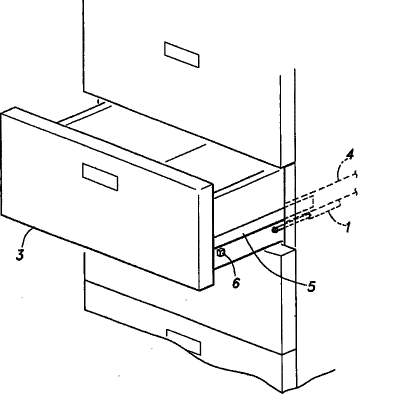
[0018] Embodiments of the present invention will be described below with reference to the accompanying drawings. figure 1 It is a perspective view which shows the external appearance important part of the cabinet 2 using the shock absorber 1 which is the shock absorber of this invention. As shown in the figure, the cabinet 2 is provided with a drawer 3 that can slide in the front. In addition, base rails 4 are fixed to the left and right side walls of the cabinet 2 in a substantially horizontal state, and the slide rails 5 are supported by the base rails 4 so as to be slidable in a direction extending and contracting with respect to the front surface of the cabinet 2 . The drawer 3 is supported by the slide rail 5 .

[0019] Furthermore, in order to alleviate the impact force when the drawer 3 is accommodated with respect to the cabinet 2, for example, the impact force when the sliding terminal stops sliding, in the illustrated example, a buffer 1 is fixedly provided at an ap...


PUM


Abstract

The invention provides a shock absorber capable of preventing deterioration of shock absorbing performance in each environment at low and normal temperatures. A piston 12 is provided in a cylinder 11 so as to move freely in the axial direction, a piston rod 13 connected integrally with the piston comes in and out of an opening face of the cylinder, and a cap 14 covering its opening is provided. An oil seal 19 having an X-shaped cross sectional shape is held by a cylindrical part 14a provided on an inner side of the cylinder of the cap, a boss part 14b is provided on an outer side of the cylinder of the cap, and a long shaft supporting hole 14c for supporting the piston rod is provided in a central part of the cap and the boss part. By using viscous fluid sealed into the cylinder and providing substantially equal shock absorbing capability even at low temperature of about -30 degrees centigrade including degree in the vicinity of 0 degree and at normal temperature, occurrence of difference in shock absorbing performance for change of temperature is prevented. By providing the seal member having the X-shaped cross sectional shape even when the viscous fluid having such shock absorbing capability has low viscosity, its leakage is prevented.

Description

technical field [0001] The present invention relates to a shock absorber of piston and cylinder configuration. Background technique [0002] Conventionally, a shock absorber has been used on the switch body relative to the main body switch for the purpose of alleviating the impact force during the switching operation and for obtaining a sense of luxury through the gentle operation. This type of buffer device is composed of a piston and a cylinder. While filling the cylinder with a viscous fluid such as silicone oil, a small hole is provided in the piston, and the resistance of the viscous fluid passing through the small hole generated by the movement of the piston exerts the buffer function (refer to Patent Document 1 - Japanese Patent No. 3465978 ). [0003] On the one hand, slidable drawers are sometimes provided in desks, cabinets, and the like. By making such a drawer supported by the main body via the slide rail, since the support rigidity of the drawer can be improve...

Claims


Application Information

Patent Timeline
Patent Type & Authority Patents(China)
IPC IPC(8): F16F9/32A47B88/57F16F9/36F16J15/3232F16J15/3236
Inventor 富地胜康稻叶蓝子
Owner NIFCO INC
Why Eureka
Try Eureka