Anti-theft alarm for electric power cable

A technology of anti-theft alarm and power cable, which is applied in the direction of anti-theft alarm mechanical start, alarm and instrument which are straightened by breaking/disturbing the rope/metal wire, etc. There are many components and parts, etc., to reduce costs, improve circuit reliability, and reduce applications

Inactive Publication Date: 2006-09-27
江苏联宏智慧能源股份有限公司
View PDF0 Cites 89 Cited by
  • Summary
  • Abstract
  • Description
  • Claims
  • Application Information

AI Technical Summary

Problems solved by technology

[0002] The safety protection of power cables is a problem that the power sector has been solving. The existing cable anti-theft alarm circuits all use a remote detection terminal with voltage detection and power carrier line communication functions installed at the end of the power cable, so the circuit is very complicated and many components a

Method used


Image

  • Anti-theft alarm for electric power cable

Examples


Embodiment Construction

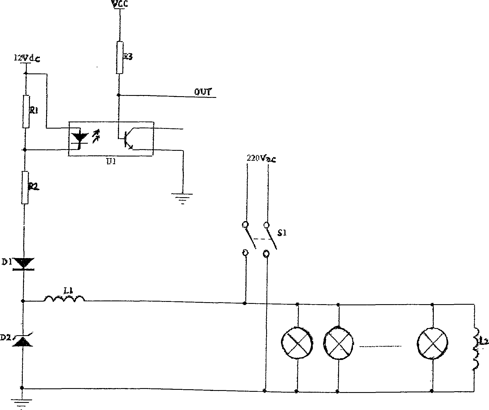
[0011] The composition and application of the power cable anti-theft alarm will be described in detail below in conjunction with the accompanying drawings. The application of the circuit: an inductor L2 is connected in parallel to the terminal. The current flows through L1 and L2 to form a loop. At this time, the diode D1 is turned on, and there is a voltage drop across R1, which makes the optocoupler U1 turn on. The low level of OUT does not trigger the LED light alarm circuit or alarm speaker connected to it. , indicating that the cable is normal; when the cable is stolen, the end inductance is disconnected from the loop, D1 and optocoupler U1 are unable to conduct, and the OUT terminal is high level to trigger the LED light alarm circuit or alarm speaker connected to it, which can indicate The cable is broken and may have been stolen.

[0012] In the state of power supply at night, that is, when S1 is closed, if there is a theft, there will be no current in the circuit, so ...


PUM


Abstract

This invention relates to an anti-theft alarm for electric power cable. Wherein, connecting an ac large-resistance inductance in series at least on two wires ends; arranging a dc detection power on wire supply end to form detection port with wire testing circuit with output linked to an alarm circuit; and connecting the detection port to wire on power supply end. This invention simplifies circuit to reduce cost and increase reliability, and brings benefit to treatment in time and loss reduction.

Description

technical field [0001] The invention relates to a power cable safety protection device, in particular to a power cable anti-theft alarm. Background technique [0002] The safety protection of power cables is a problem that the power sector has been solving. The existing cable anti-theft alarm circuits all use a remote detection terminal with voltage detection and power carrier line communication functions installed at the end of the power cable, so the circuit is very complicated and many components are used. , high cost, low reliability, and because the radio method is affected by the terrain environment (mountainous or remote areas), it is difficult to popularize and apply in a large area, and the anti-theft alarm device used for street lamps and 10KV / 0.4KV transformer side power cables also needs There are reliable and low cost devices. Contents of the invention [0003] The object of the present invention is: in order to solve the above problems, a safety protection d...

Claims


Application Information

Patent Timeline
IPC IPC(8): G08B13/12G01R31/02
Inventor 吴宝财吴晓龙王戎周淑华
Owner 江苏联宏智慧能源股份有限公司
Why Eureka
Try Eureka