

Joint
A push rod and cone technology, applied in the field of joints, can solve problems such as cracking of the pressure sensor connection nut 20 or the bell mouth copper pipe connection nut 40
- Summary
- Abstract
- Description
- Claims
- Application Information
AI Technical Summary
Problems solved by technology
Method used
Image

Examples
Embodiment Construction
[0117] (Structure of joint)
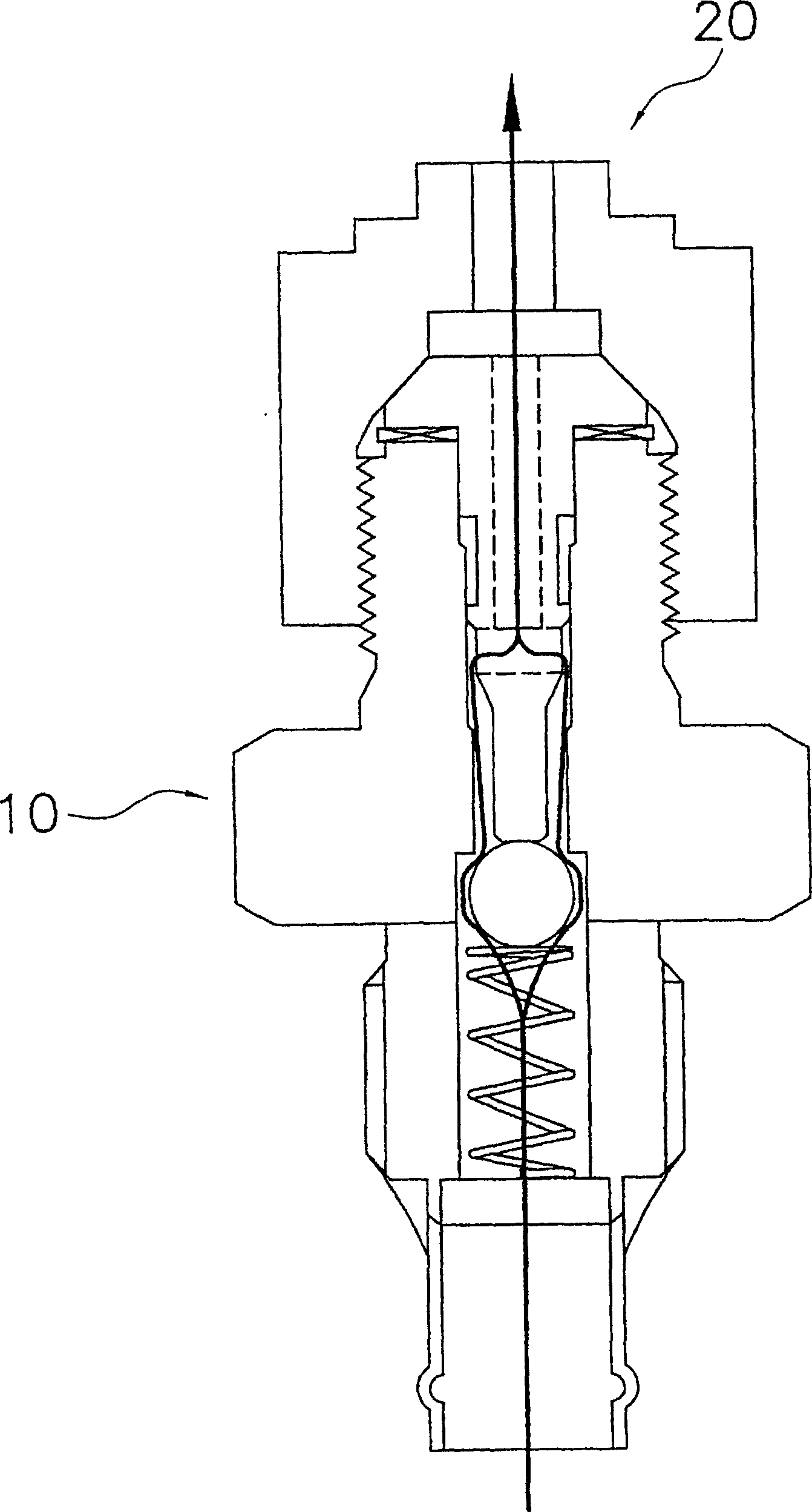
[0118] Fig. 2(a) is a longitudinal sectional view of the joint according to the present invention.
[0119] As shown in FIG. 2( a ), the joint 50 is composed of a push rod 52 , a main body 51 , a steel ball 55 , a spring 56 and a copper pipe portion 57 .
[0120] (Constituent elements of joints)
[0121] (1) putter
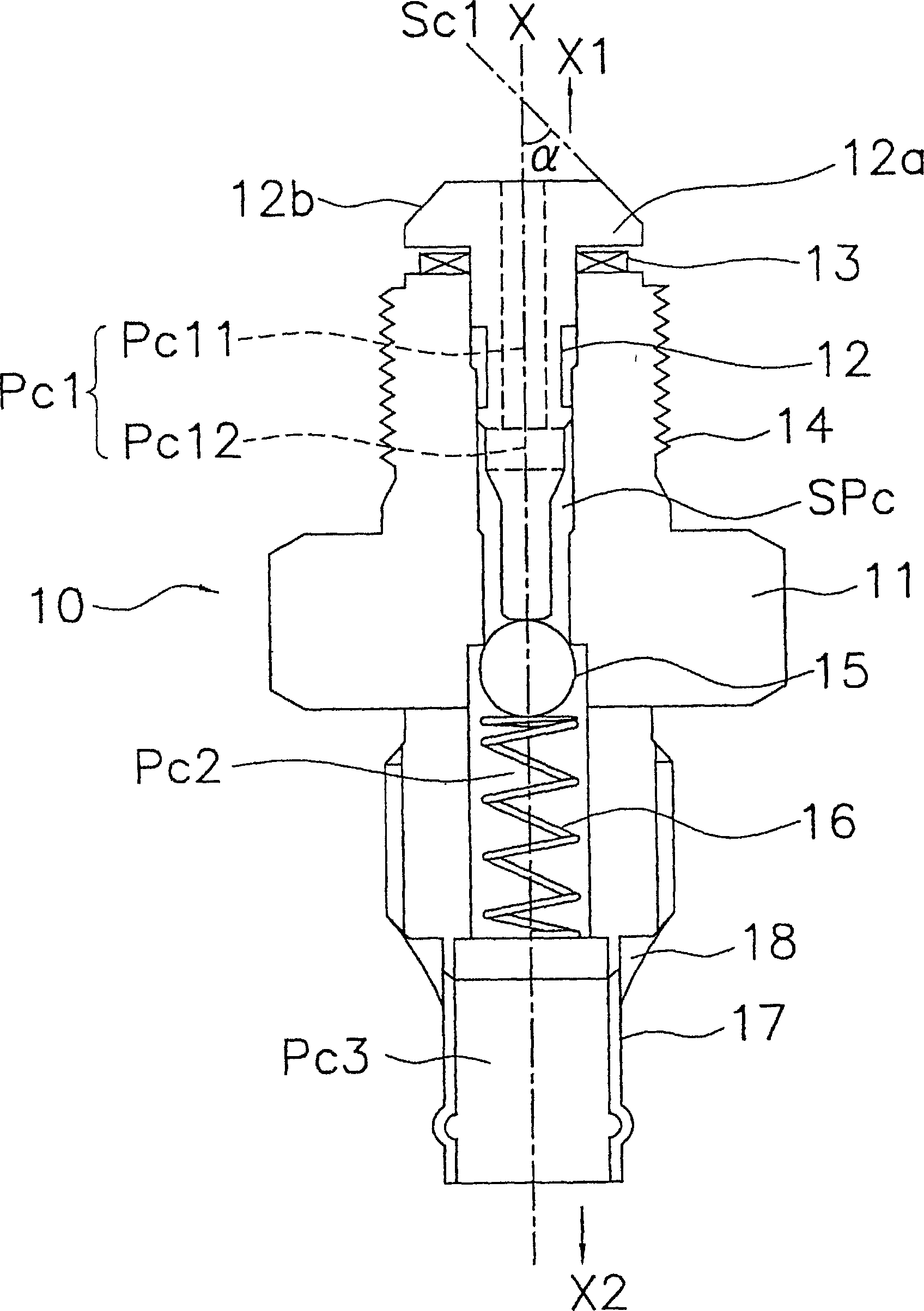
[0122] The push rod 52 has the protrusion part 52a, the 1st flow path Pi11, and the 2nd flow path Pi12. The protrusion part 52a is provided in the outer periphery of the push rod 52, and has the protrusion taper part 52b. Moreover, this protrusion taper part 52b inclines toward the side X2 opposite to the push rod protruding side of the push rod longitudinal direction X as it approaches the outer peripheral side. In addition, the protruding tapered portion 52b is formed such that the angle formed by the inclination direction of the protruding tapered portion 52b and the push rod longitudinal direction X is smaller than or equal to...
PUM
 Abstract
Description
Claims
Application Information