Rear suspension for turbojet engine

A technology on jet engines and brackets, which is applied in the directions of power units, jet power units, and aircraft parts on aircraft to achieve the effect of simplifying geometric shapes

Active Publication Date: 2006-10-04
SN DETUDE & DE CONSTR DE MOTEURS DAVIATION S N E C M A
View PDF1 Cites 21 Cited by
  • Summary
  • Abstract
  • Description
  • Claims
  • Application Information

AI Technical Summary

Problems solved by technology

[0009] The applicant's purpose is to produce a suspension that will perform the same function as the suspensi

Method used


Image

  • Rear suspension for turbojet engine
  • Rear suspension for turbojet engine
  • Rear suspension for turbojet engine

Examples


Embodiment Construction

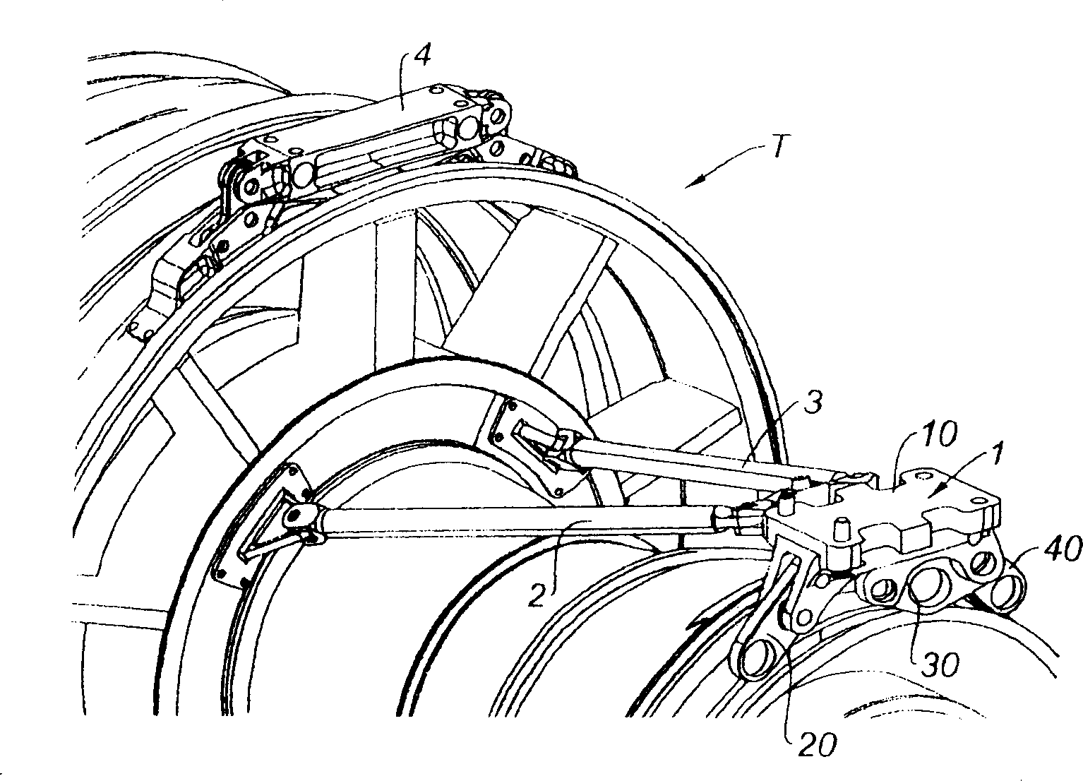
[0021] figure 1 Is a rear three-quarter view of a jet engine T equipped with a connection to an aircraft mount (not shown). In particular, the engine may be connected to an aircraft wing. According to this suspension method, the engine comprises a connection device 4 in front of the engine, which is fastened to the intermediate fan case. It also includes connection means 1 at the rear, which is connected to the main exhaust casing. The thrust is absorbed by two rods 2 and 3, arranged longitudinally on either side of the engine shaft and connected at their ends, on the one hand to the hub of the fan housing and on the other hand to the rear Connectors.

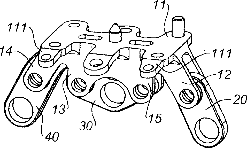
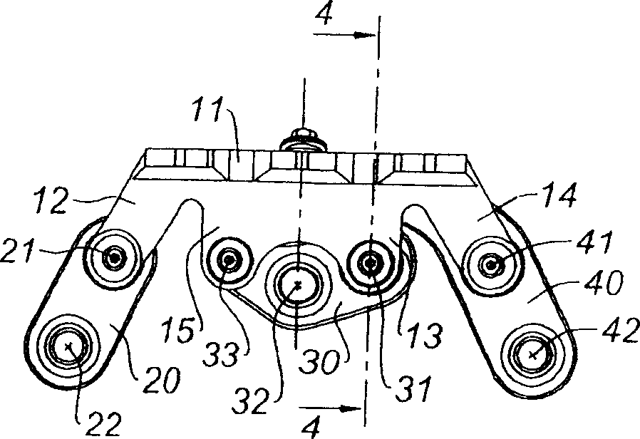
[0022] The following description refers to the rear connection 1 . From figure 2 and image 3 It can be seen that the connection comprises a beam 10 for fastening to a bracket or pylon of the aircraft, and three connection parts 20, 30, 40 connecting this beam 10 to a clevis fastened to the engine case . These clevis a...


PUM


Abstract

The invention discloses a suspension for suspending a jet engine on an aircraft support, comprising a beam (10) with a platform (11), a first side connection (20) and a second side connection (40), The second side connector (40) extends into the area of ​​the first pin by fingers (43) interstitially embedded in holes provided in the beam to form a backup safety connection; an intermediate connection (30) between side connections (20, 40), said beam comprising a clevis (13) for receiving said first connection pin (31 ) of said central connection (30), The first pin has a distance from the platform (11) so as to form a space between said platform (11) and said central connection (30), which space constitutes said hole, said second side in normal operation. Said fingers (43) of the connector (40) engage in said holes with clearance. The solution of the invention makes it possible to reduce the weight of the suspension and to simplify the corresponding machining.

Description

technical field [0001] This invention relates to the field of jet engines and in particular to suspensions on the structure of jet engine propelled aircraft. Background technique [0002] Propulsion engines, such as jet engines, may be mounted at various locations on the aircraft by being connected to brackets or pylons belonging to the aircraft structure. It can thus be hung under the wing, fastened to the fuselage, usually at the rear, or mounted in the aft section using suitable attachment means. The function of these connecting means is to ensure the transmission of mechanical forces between the engine and the aircraft structure. The loads to be considered are positioned in the three main directions of the frame of reference combined with the engine. In particular, the weight of the engine is along the vertical axis Z, its thrust is along the engine axis X, and the lateral aerodynamic loads are along the transverse axis Y. The load to be transmitted also includes the ...

Claims


Application Information

Patent Timeline
IPC IPC(8): B64D27/16
CPCB64D27/26B64D2027/266B64D2027/268Y02T50/44Y02T50/40
Inventor 塞比斯蒂恩·德朗恩泽博·吉伯特格雷格利·普鲁德豪姆马克·泰斯尼尔
Owner SN DETUDE & DE CONSTR DE MOTEURS DAVIATION S N E C M A
Why Eureka
Try Eureka