Machine vise attachment

a machine tool and attachment technology, applied in the direction of metal-working machine components, manufacturing tools, metal-working apparatus, etc., can solve the problems of difficult to clamp the parts in the jaws of each jaw set at the same time, difficult to load, and difficult to do with ordinary machine tool vises mounted on a machine tool table. , to achieve the effect of improving machining capabilities, preventing machining, and easy to s

Active Publication Date: 2015-11-24
KURT MANUFACTURING COMPANY INC
View PDF81 Cites 4 Cited by
  • Summary
  • Abstract
  • Description
  • Claims
  • Application Information

AI Technical Summary

Benefits of technology

[0004]The auxiliary vise is mounted on a bracket that offsets the clamping jaws of the auxiliary vise from the main machine vise so that work pieces can be independently clamped in each of the vises, and used for machining a work piece held in one set of jaws without interfering with the work piece held in the other set of jaws. The auxiliary vise includes a stabilizer for attaching to the tool table or support to rigidly hold the auxiliary vise in position so vibrations are greatly reduced. The auxiliary vise provides an adequate securing force for elongated work pieces that extend vertically alongside the tool table on which the vises are mounted.
[0006]The positioning of the auxiliary vise is elevated from the machine tool table on which the vises are mounted to provide a vise jaw location that is more conducive to holding elongated work pieces, and provides clearance for machining. Even with the auxiliary vise mounted on the main machine vise, there is no interference with the set up or changing of jaw plates on the main machine vise, and the auxiliary vise likewise can be operated separately. The auxiliary vise is positioned laterally of the main machine vise so that it does not impede the machining area of the main machine vise such that the duplex vise assembly set up enhances machining capabilities, and does not impede machining in most applications.
[0007]The jaws of the main machine vise and of the auxiliary vise are separated sufficiently, and in the line of operator view so that the operator can easily see the work pieces that are being clamped and machined in either or both vises, and the operator can easily load and unload such work pieces.

Problems solved by technology

In many instances, it is desirable to hold elongated work pieces in a vertical position for machining on ends and the like, and it is difficult to do with ordinary machine vises mounted on a machine tool table.
An attachment for a shaper vise that provides auxiliary jaws is shown in U.S. Pat. No. 1,971,069, but this unit is mounted directly onto the end of a vise, making it difficult to load and also difficult to have parts clamped in the jaws of each of the sets of jaws at the same time.

Method used


Image

  • Machine vise attachment
  • Machine vise attachment
  • Machine vise attachment

Examples


Embodiment Construction

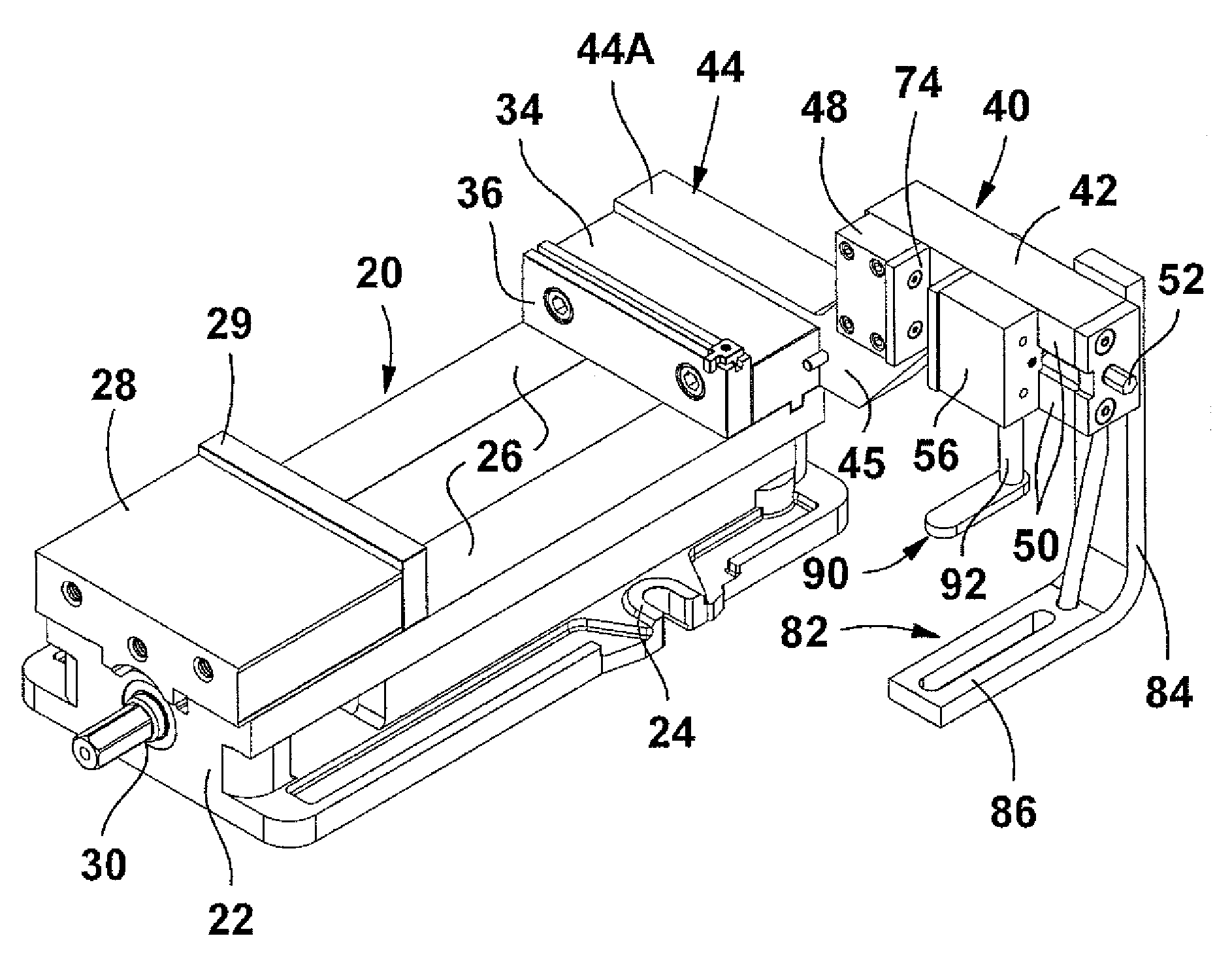
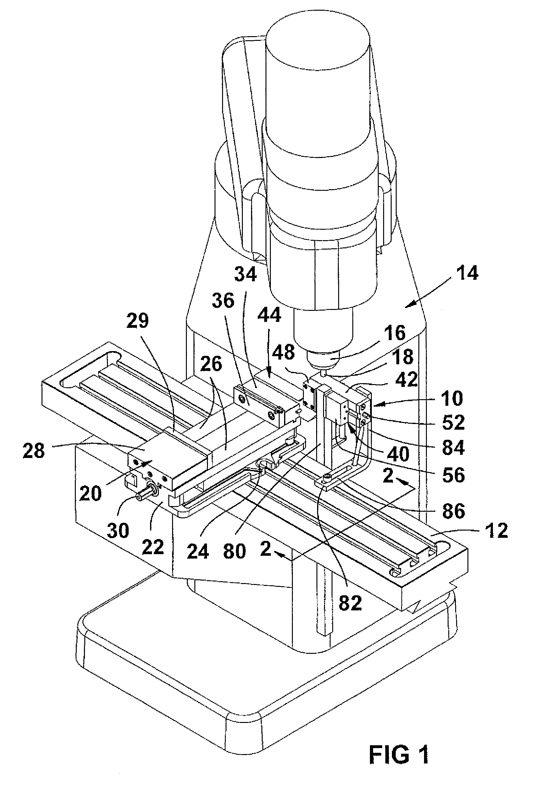
[0017]In FIG. 1, a duplex vise assembly indicated generally at 10 is shown installed on a machine tool table 12 of a machine tool 14. The machine tool 14 has a rotatably driven spindle 16 and a rotating tool 18 that is used for machining work pieces. The duplex vise assembly includes a main machine vise 20 of conventional design that includes the vise body 22 having flanges 24 that are secured to the tool table 12 in a conventional manner with T-shaped hold down bolts. The vise body 22 is supported and held securely on the tool table so that the guide surfaces or guideways 26 for guiding a movable jaw 28 of the main machine vise form a plane parallel to the upper surface of the tool table 12. The movable jaw 28 has a changeable jaw plate 29 thereon, and is driven utilizing a vise screw 30, driving a vise jaw nut 32 (FIG. 3) in a conventional manner to move the movable vise jaw 28 toward and away from a fixed jaw 34, which includes a changeable jaw plate 36. The main machine vise 20 ...


PUM


Abstract

A main machine vise has a second auxiliary vise having independently movable clamping jaws attached to it with the auxiliary vise set to one side of the main machine vise and above a supporting surface of a machine tool table on which the main machine vise is mounted. The auxiliary vise has a movable jaw that moves in a plane generally perpendicular to the tool table on which it is mounted, while the main machine vise has a movable jaw that moves in a plane parallel to the tool table or surface on which it is mounted. The auxiliary vise is mounted on a bracket that offsets the clamping jaws of the auxiliary vise from the main machine vise so that work pieces can be independently clamped in each of the vises. The auxiliary vise includes a vibration reducing stabilizer for attaching to the tool table or support.

Description

BACKGROUND OF THE DISCLOSURE[0001]The present invention relates to an auxiliary machine vise attachment which transforms a machine vise into a duplex or double vise capable of holding two work pieces with a movable clamping jaw on a first or main machine vise moving in a plane generally horizontal to a machine tool table supporting the vises, and the auxiliary vise having a movable clamping jaw moving in a plane perpendicular to the machine tool table. The movable jaw of the auxiliary vise slides on guideways which are positioned relative to a cylindrical bore which precisely guides the moveable jaw of the auxiliary vise as the work piece is clamped.[0002]In many instances, it is desirable to hold elongated work pieces in a vertical position for machining on ends and the like, and it is difficult to do with ordinary machine vises mounted on a machine tool table. The main orientation for mounting machine vises is with a width dimension of the jaws and the plane for support of the wor...

Claims


Application Information

Patent Timeline
Patent Type & Authority Patents(United States)
IPC IPC(8): B23Q3/02B25B1/24B25B1/10B23Q39/02
CPCB25B1/2405B25B1/103B25B1/2468B25B1/2473B25B1/2484B25B1/2489B23Q39/02
Inventor SCHMIDT, DAVID L.
Owner KURT MANUFACTURING COMPANY INC
Why Eureka
Try Eureka