Method and device for drying fiber material

A fiber material and drying technology, applied in the direction of drying gas arrangement, combustion method, heating device, etc., can solve the problems of adjusting the temperature lag of the process gas flow and reducing the efficiency of the drying device

Inactive Publication Date: 2006-10-04
HAUNI MASCHINENBAU AG
View PDF1 Cites 11 Cited by
  • Summary
  • Abstract
  • Description
  • Claims
  • Application Information

AI Technical Summary

Problems solved by technology

A decrease in the mass flow rate of the process gas flowing through the above-mentioned regulating bypass leads to an increase in the temperature of the tube walls in the heat exchanger, which, due to the high inertia of the heat exchanger, leads to a significant lag in regulating the temperature of the process gas stream, resulting in the drying unit Reduced efficiency

Method used


Image

  • Method and device for drying fiber material

Examples


Embodiment Construction

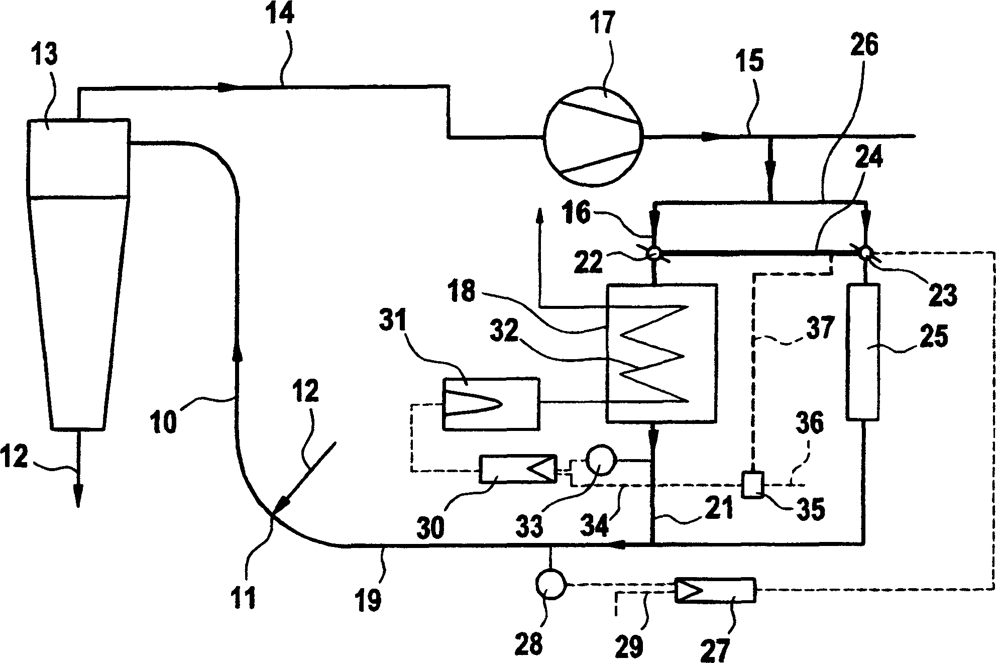
[0010] exist figure 1 This drying apparatus shown in includes a tubular airflow dryer with or without a steam section, in particular hot air or hot steam (superheated steam) at a temperature between 130°C and 150°C flowing through the hot process gas 10. The airflow dryer 10 is a part of the pipeline through which the process gas flows in the direction of the arrow. The air dryer 10 comprises a product inlet 11 for the tobacco 12 to be dried. The tobacco 12 is conveyed by the process gas flow and in the process is dried in the air dryer 10 . The dried tobacco is separated by a separator 13 from the hot air which is conveyed by a compressor 17 to a heat exchanger 18 through pipes 14-16. Through the heat exchanger 18, the process gas is heated to the required drying temperature to recover the heat extracted by the drying process. For this purpose, heat is transferred to the above-mentioned heat exchanger 18 by means of a combustion-supporting gas flow 32 generated by the bur...


PUM


Abstract

The application concerns a method for drying a fibrous material by means of a process gas stream flowing through a pipe, including heating the process gas flowing through the pipe by means of a heater with controllable heating power, and conducting a portion of the process gas stream through a bypass pipe bypassing the heater, wherein the ratio of mass flows of process gas flowing through the heater and through the bypass pipe is adjustable, and is distinguished by the fact that the heating power of the heater is controlled according to the set ratio of mass flows of process gas through the heater and through the bypass pipe. The application further concerns a corresponding drying apparatus.

Description

technical field [0001] The invention relates to a method and a device for drying fibrous material according to the preambles of claims 1 and 12 . Background technique [0002] This device is known from DE3305670C2 and comprises a regulation bypass and a second parallel backup bypass. The process gas mass flow through the regulating bypass is regulated according to the temperature of its carrier. Fuel and combustion air to the burner are regulated according to the temperature of the tube gas produced by the burner. The burner ballast air is adjusted according to the temperature of the process gas stream after the heat exchanger. A decrease in the mass flow rate of the process gas flowing through the above-mentioned regulating bypass leads to an increase in the temperature of the tube walls in the heat exchanger, which, due to the high inertia of the heat exchanger, leads to a significant lag in regulating the temperature of the process gas stream, resulting in the drying un...

Claims


Application Information

Patent Timeline
Patent Type & Authority Applications(China)
IPC IPC(8): F26B23/10F26B23/02F26B21/12
CPCF23N2025/21F26B17/101F26B2200/22A24B3/04F23N1/082F26B21/10F23N2225/21
Inventor T·科赫
Owner HAUNI MASCHINENBAU AG
Why Eureka
Try Eureka