Multi-mode internal imaging

An imaging, optical imaging technology used in research and imaging applications to solve problems such as difficulty in maintaining spatial accuracy and difficulty in movement

Inactive Publication Date: 2006-10-04
色诺根公司
View PDF3 Cites 14 Cited by
  • Summary
  • Abstract
  • Description
  • Claims
  • Application Information

AI Technical Summary

Problems solved by technology

Also, moving the object to be imaged between the different imaging systems will be difficult, e.g., maintaining the spatial accuracy provided by each system without the trade-offs caused by the movement of the object between the systems

Method used


Image

  • Multi-mode internal imaging
  • Multi-mode internal imaging
  • Multi-mode internal imaging

Examples


Embodiment Construction

[0032] In the following detailed description of the invention, numerous specific embodiments are set forth in order to provide a thorough understanding of the invention. However, the invention may be practiced without these specific details or with alternative elements or processes, as will be apparent to those skilled in the art. In other instances, known processes, components, and designs have not been described in detail so as not to unnecessarily obscure aspects of the invention.

[0033] 1. Overview

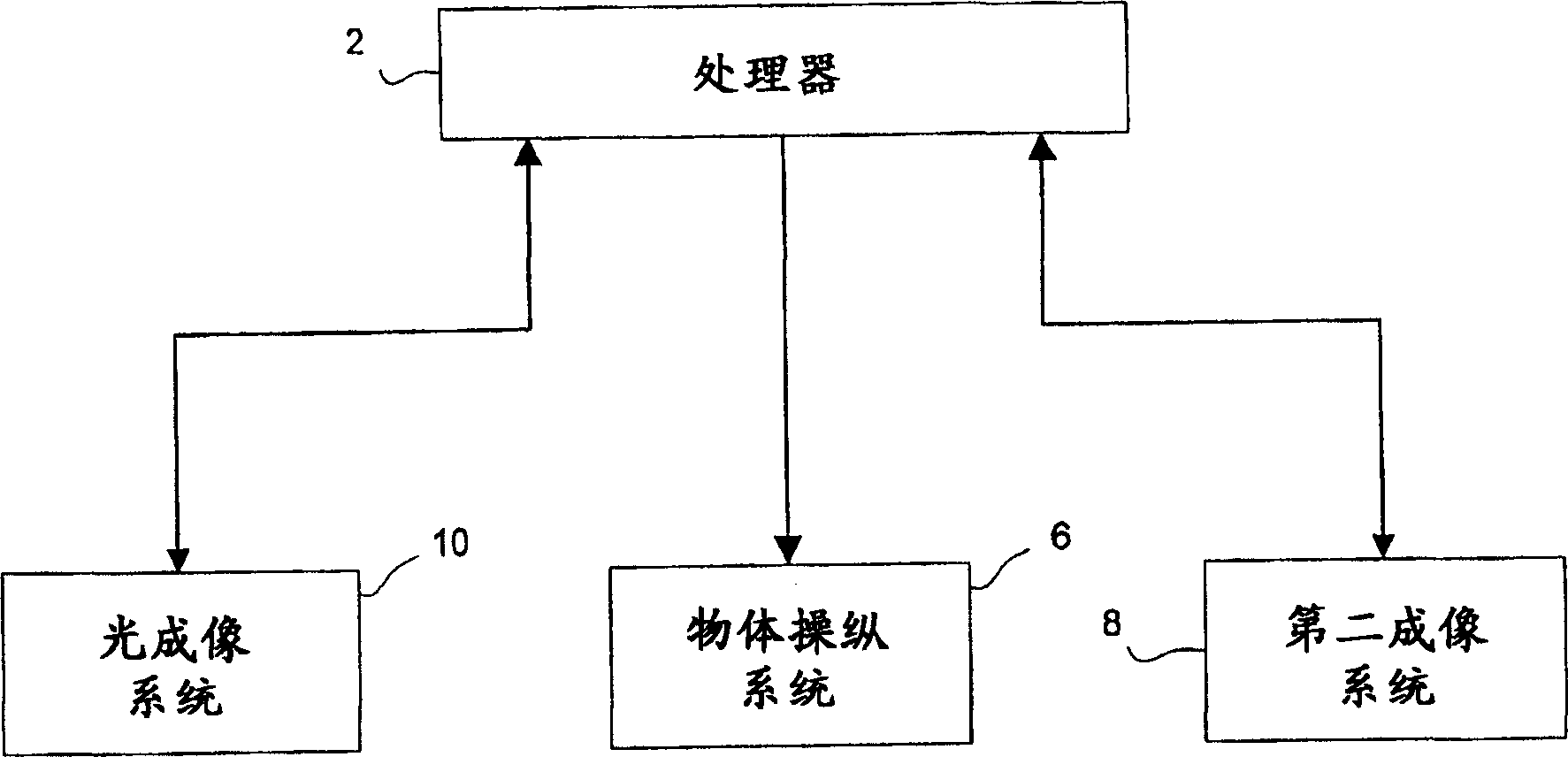
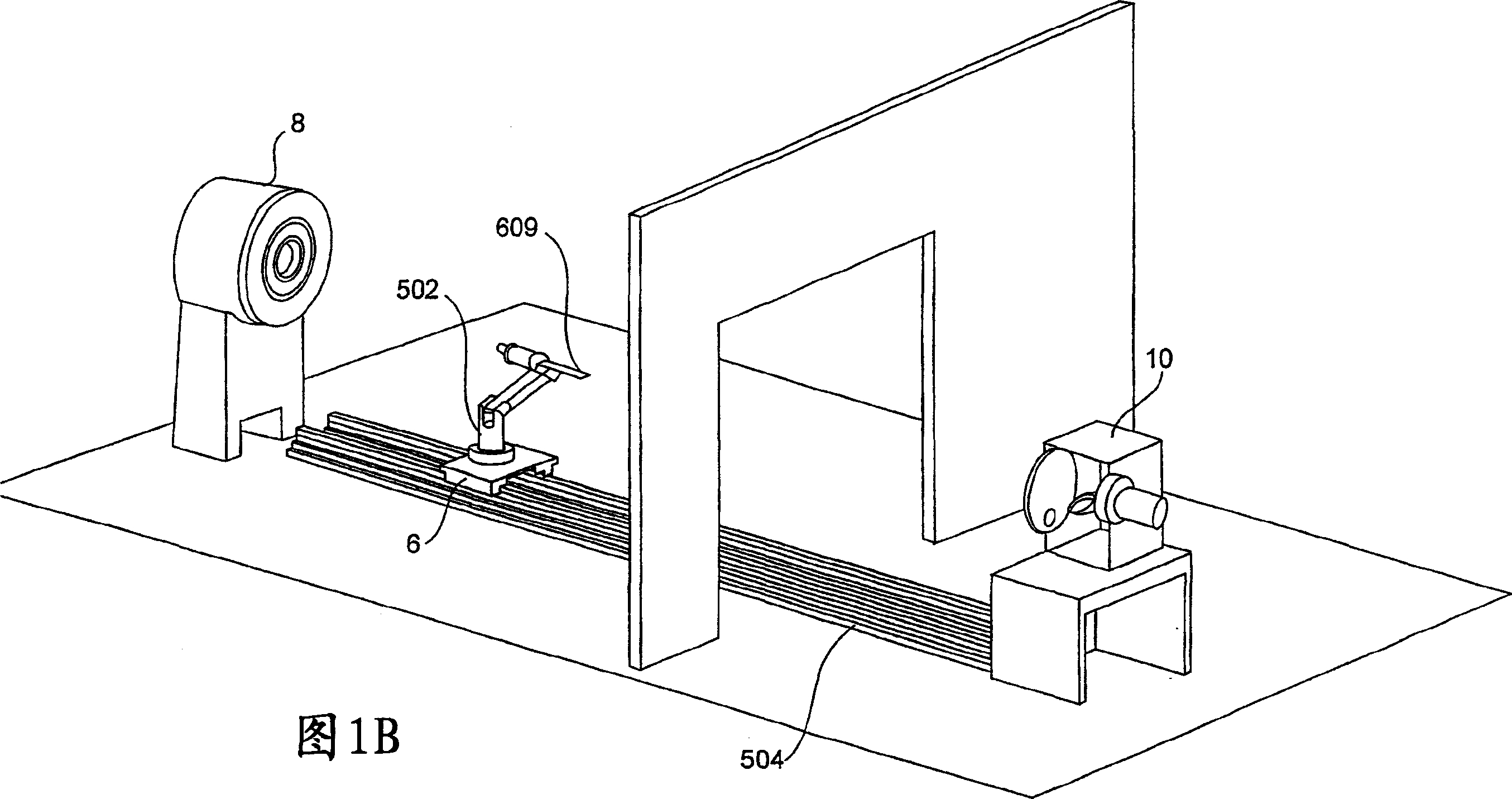
[0034] Figure 1AA simplified system 1 for providing multimodal imaging data inside an object according to an embodiment of the invention is illustrated. System 1 includes an optical imaging system 10 , a second imaging system 8 , an object manipulation system 6 , and at least one processor 2 . The object manipulation system 6 moves the object (or sample) being imaged between the lumen of the optical imaging system and the receiving area of ​​the second imaging system. Al...


PUM


Abstract

The invention described herein provides systems and methods for multi-modal imaging with light and a second form of imaging. Light imaging involves the capture of low intensity light from a light-emitting object. A camera obtains a two-dimensional spatial distribution of the light emitted from the surface of the subject. Software operated by a computer in communication with the camera may then convert two-dimensional spatial distribution data from one or more images into a three-dimensional spatial representation. The second imaging mode may include any imaging technique that compliments light imaging. Examples include magnetic resonance imaging (MRI) and computer topography (CT). An object handling system moves the object to be imaged between the light imaging system and the second imaging system, and is configured to interface with each system.

Description

Technical field: [0001] The present invention relates to systems and methods for acquiring multiple image representations of the interior of an object, particularly for research and imaging applications. More specifically, the invention relates to multimodal imaging and other types of imaging using light. Background technique [0002] Currently, researchers and imaging physicians use any of a variety of noninvasive imaging techniques to produce internal images. These techniques use X-rays, magnetic resonance imaging (MRI), CAT scans, and ultrasound. In other systems, optical imaging is used to generate an optical image of an object. For example, bioluminescent imaging is a non-invasive technique used in the fields of medical research, pathology, and drug discovery and development to perform in vivo diagnostic studies on animal test subjects. Bioluminescence is generally produced by cells transfected with a luminescent indicator such as luciferase, which can be used to dis...

Claims


Application Information

Patent Timeline
Patent Type & Authority Applications(China)
IPC IPC(8): A61B5/05
Inventor 麦克尔·D.·卡贝尔布雷德利·W.·莱斯戴维·尼尔森
Owner 色诺根公司
Why Eureka
Try Eureka