Circuit board and socket assembly

A technology for printed circuit boards and sockets, applied in the direction of circuits, electrical components, parts of connecting devices, etc., can solve problems such as damage to device performance, no overall satisfactory solution found, disadvantage, etc.

Inactive Publication Date: 2006-10-04
AMPHENOL CORP
View PDF3 Cites 6 Cited by
  • Summary
  • Abstract
  • Description
  • Claims
  • Application Information

AI Technical Summary

Problems solved by technology

[0008] The problem with the pin contact disclosed by Bright et al. is to achieve electrical continuity at the very far end of the contact, which is not feasible if it is used to electrically connect a printed circuit board
[0012] The problem with the contact pin disclosed by Birnholz is that the rigid metal barb of the contact exerts force on the plastic hole during insertion of the contact causing it to separate
This will create internal stresses inside the PCB near the vias, compromising the performance of the device
Also, the contact through-hole receiver forms a rigid connection with the contact, which is disadvantageous in some applications as previously described
[0013] None of the various solutions for making solderless interconnections described in the above cited patents found an overall satisfactory solution

Method used


Image

  • Circuit board and socket assembly
  • Circuit board and socket assembly
  • Circuit board and socket assembly

Examples


Embodiment Construction

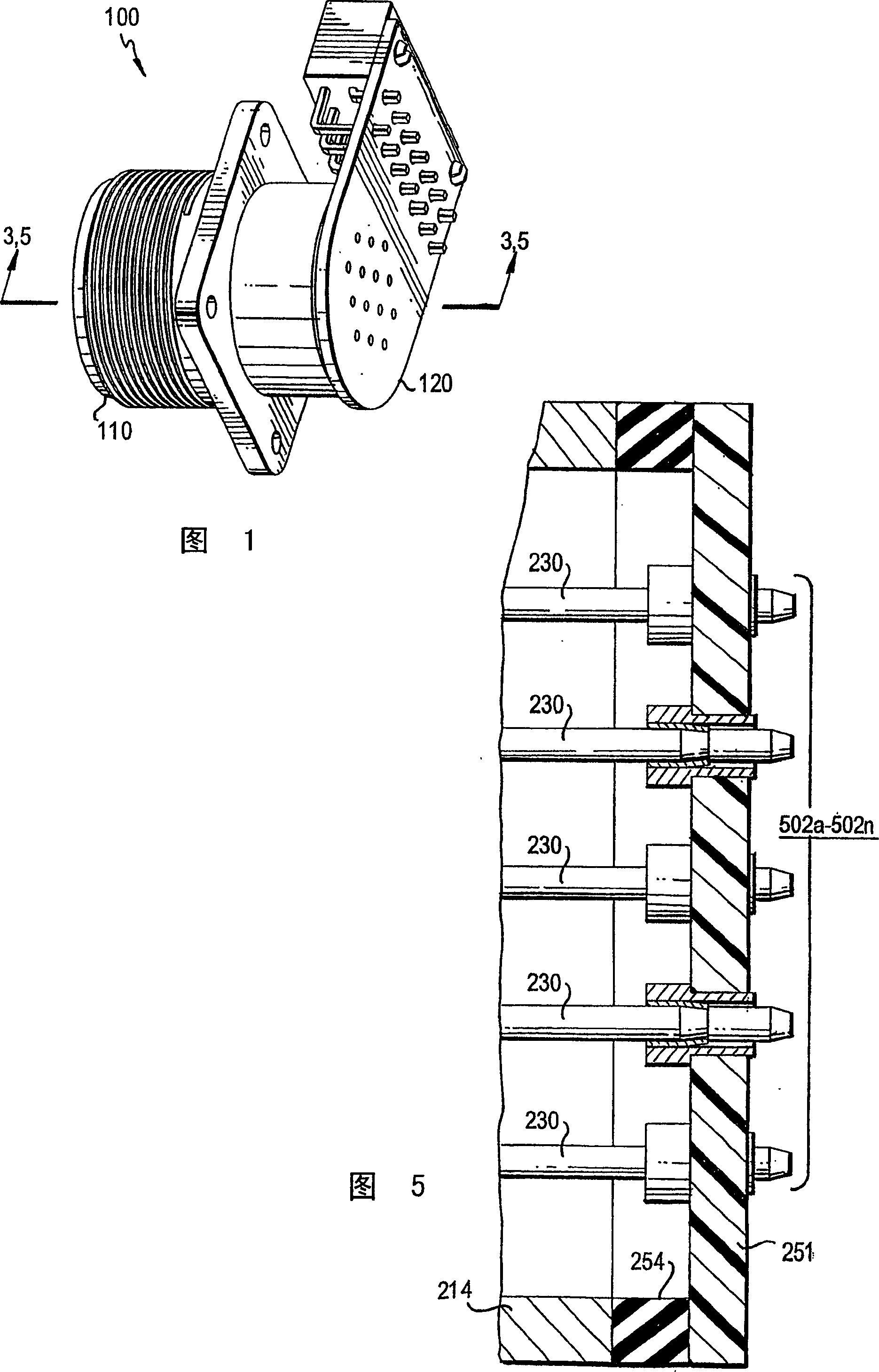
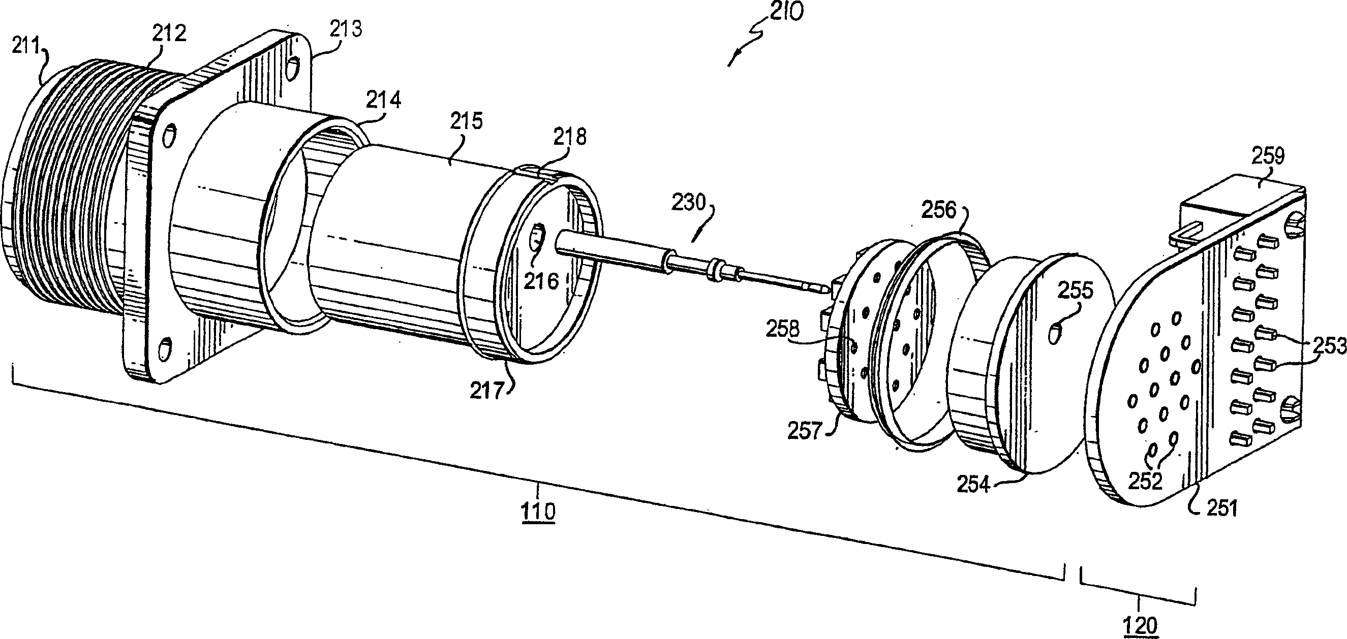
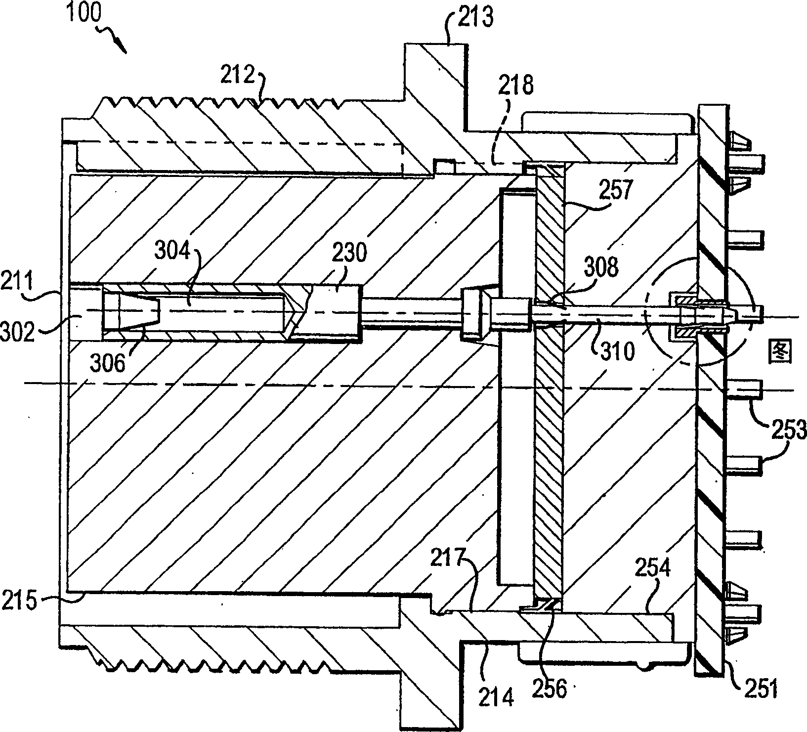
[0027] Referring now to the detailed description of the drawings, wherein like parts are indicated by like reference numerals, a perspective view of an electrical connector 100 of the present invention is shown in FIG. . Connector 100 in FIG. 1 illustrates how the receptacle and printed circuit board embodiment of the present invention may be used in a typical application. However, those skilled in the art will appreciate that any connector including a receptacle receiver, a pin receiver, or the interconnection of a plug and a printed circuit board can be implemented with the present disclosure, and that the invention can be used well in many contexts or used in aircraft. For example, the jack receiver embodiment shown in FIG. 1 may be adapted to accept plugs of any shape, not just round.

[0028] In the context of the present invention, the term "socket" may be interchanged with "adapter" or "receiver". These terms, and others commonly used in the art, generally refer to r...


PUM


Abstract

An interconnect device and electrical signal filtering connector is disclosed that does not require soldering. The interconnect device is an electrical contact that has a proximate or forward end with a cavity for receiving an electrical conductor of a first plug, and a distal or rear end, also called a tail, formed with a circumferentially-arranged undercut that engages the ends of one or more electrically conducting flanges that extend radially inward in a contact receptacle of a printed circuit board. The connector can be a male plug or female receptacle, including a receptacle with front and rear shells and an insert slidably engaged inside the shells, the receptacle adaptable for receiving a round, 14-conductor plug. The printed circuit board assembly includes a printed circuit board with one or more contact receptacles.

Description

technical field [0001] The present invention generally relates to electrical connectors. In particular, the present invention relates to a method and system for interconnecting a printed circuit board to the rear of an electrical socket or plug. Background technique [0002] The present method and system for connecting a printed circuit board to the rear of an electrical receptacle and plug connector includes soldering the connector contact tails to the circuit board. The purpose of the welding operation is to provide electrical and mechanical connections. In some cases, the heat generated by the soldering process may adversely affect the connector and printed circuit board. As a result, the electrical performance of the interconnect may be irreparably damaged, or at least significantly degraded. Of course, performance degradation must be avoided in electronic devices used in avionics and other sensitive systems, especially where stringent specifications must be met. [...

Claims


Application Information

Patent Timeline
Patent Type & Authority Applications(China)
IPC IPC(8): H01R12/00H01R13/187H01R13/502H01R13/66
CPCH01R13/187H01R12/58H01R13/502H01R13/6625
Inventor L·A·小克兰茨J·D·马尼昂
Owner AMPHENOL CORP
Why Eureka
Try Eureka