
Aspherical focusing lens

An aspheric surface and lens technology, applied in the field of lenses, can solve problems such as not being able to eliminate aberrations well, and achieve the effect of small refractive index error and easy manufacturing

Inactive Publication Date: 2006-10-11
HONG FU JIN PRECISION IND (SHENZHEN) CO LTD +1
View PDF2 Cites 5 Cited by
  • Summary
  • Abstract
  • Description
  • Claims
  • Application Information

AI Technical Summary

Problems solved by technology

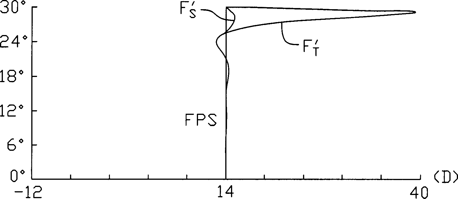
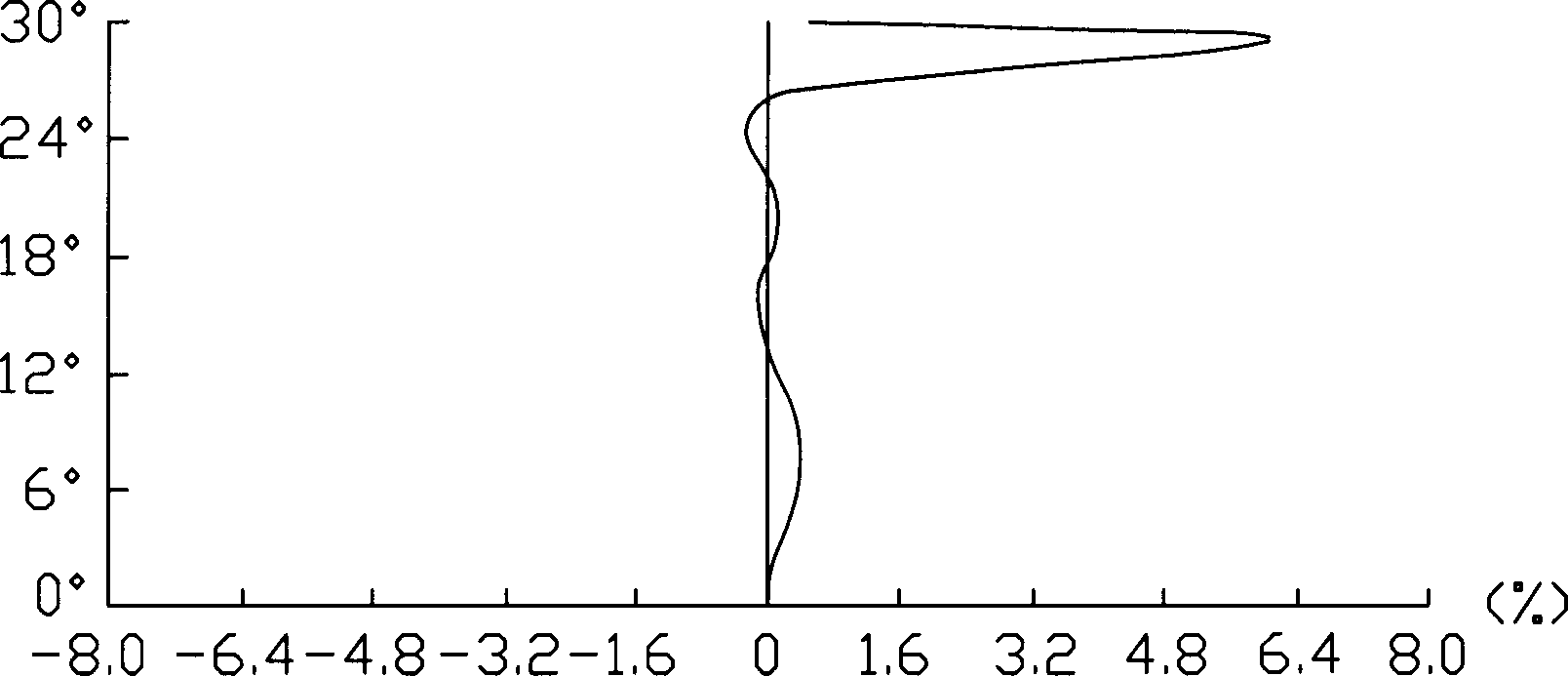
[0034] Therefore, the aspheric converging lens is optimized with five or six fields of view, which cannot eliminate aberrations well.

Method used


Image

  • Aspherical focusing lens
  • Aspherical focusing lens
  • Aspherical focusing lens

Examples


Embodiment Construction

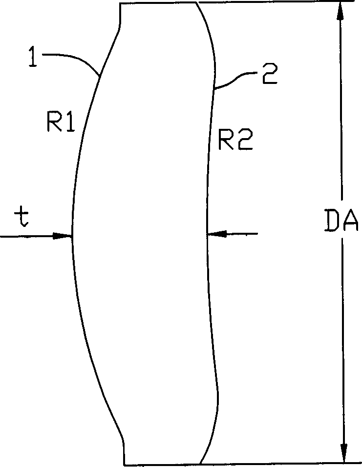
[0047] Such as figure 2 Shown is a schematic diagram of the structure of the aspheric converging lens of the present invention, the aspheric converging lens includes a first aspheric surface 1 and a second aspheric surface 2, and the radius of curvature of the first aspheric surface 1 is R 1 , the radius of curvature of the second aspheric surface 2 is R 2 , the thickness of the center of the lens is t, and the diameter of the lens is DA.

[0048] The aspherical converging lens of the present invention adopts damping least square method to optimize the design. In the performance function (3), the process of correcting the aberration to the target value by the design of the aspheric converging lens of the present invention is expressed as having 10 variable design parameters, that is, 10 design variable performance functions. with x 1 、x 2 、x 3 ,...,x 10 The aspheric surface representing the first aspheric surface 1 is the number P 1 , B 1 、C 1 、D 1 ,E 1 The number ...


PUM


Abstract

The invention discloses an aspheric surface collective lens, which comprises the first aspheric surface and the second aspheric surface. Wherein the refractive index change is in 1D range; the first aspheric surface is fixed; the invention has at least 7 visual fields, to make the target ti zero of performance function (as formula), while wi is weight factor, m is optimized term number, ei is one optical aberration and ti is the target of one optical aberration value.

Description

【Technical field】 [0001] The invention relates to a lens, in particular to an aspherical lens. 【Background technique】 [0002] At present, the lenses used in optical devices such as optical reading heads, camera lenses, and spectacle lenses generally include spherical lenses or aspheric lenses. [0003] For spherical lenses, since the two refractive surfaces are spherical, it is easier to manufacture and process. However, for spherical converging lenses with a thick center and thin edges, as the refractive index (also called power) of the lens increases, the center of the lens will thicken significantly. The refractive index of the lens refers to the back vertex value of the lens, and its value is equal to the reciprocal of the paraxial back vertex focal length of the lens measured in meters (the distance from the vertex of the lens' image-side surface to the image-side focus). It can be calculated by formula (1): [0004] F v ...

Claims


Application Information

Patent Timeline
IPC IPC(8): G02B13/18
Inventor 孙文信
Owner HONG FU JIN PRECISION IND (SHENZHEN) CO LTD
Learn More