
Bidirectional three-level soft switch DC/DC for superconducting energy storage and its current side phase-shift controlling method

A superconducting energy storage and soft switching technology, applied in control/regulation systems, high-efficiency power electronic conversion, electrical components, etc., can solve the problems of shortening the life of the switching tube, bulky, increasing system cost, etc., and achieve the speed of charge-discharge conversion. Fast, simple control method, and the effect of solving the unbalanced midpoint voltage

Inactive Publication Date: 2006-10-11
INST OF ELECTRICAL ENG CHINESE ACAD OF SCI
View PDF3 Cites 10 Cited by
  • Summary
  • Abstract
  • Description
  • Claims
  • Application Information

AI Technical Summary

Problems solved by technology

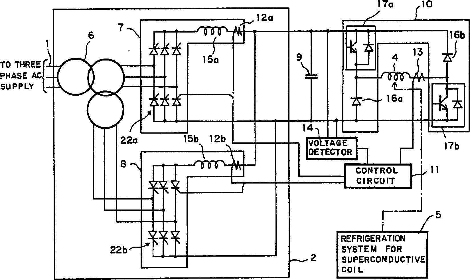
Although these patents adopt different topological structures, they do not solve two key problems: 1. The soft switching problem of the switching tube
These DC / DCs realize the charging and discharging of superconducting magnets through hard switching. The switching stress and loss of the switching tube are large, which not only greatly shortens the life of the switching tube, but also reduces the working efficiency of the system.
2. The DC voltage terminal voltage is low, and there is only one DC terminal voltage interface, which cannot be connected with advanced multi-level voltage source inverters
It realizes the charging and discharging of the superconducting magnet through the hard switching of the switch tubes 17a and 17b, the stress of the switch tube is large, and the loss is also large; at the same time, it has only one DC terminal voltage interface, as shown in the figure, the two ends of the capacitor 9 The DC voltage interface provided, in order to reduce harmonics, it can only be connected to the high voltage power system through multiple voltage source converters
However, multiple voltage source converters need to use multiple bulky and expensive power frequency transformers
Not only greatly increases the volume of the system, but also greatly increases the cost of the system

Method used


Image

  • Bidirectional three-level soft switch DC/DC for superconducting energy storage and its current side phase-shift controlling method
  • Bidirectional three-level soft switch DC/DC for superconducting energy storage and its current side phase-shift controlling method
  • Bidirectional three-level soft switch DC/DC for superconducting energy storage and its current side phase-shift controlling method

Examples


Embodiment Construction

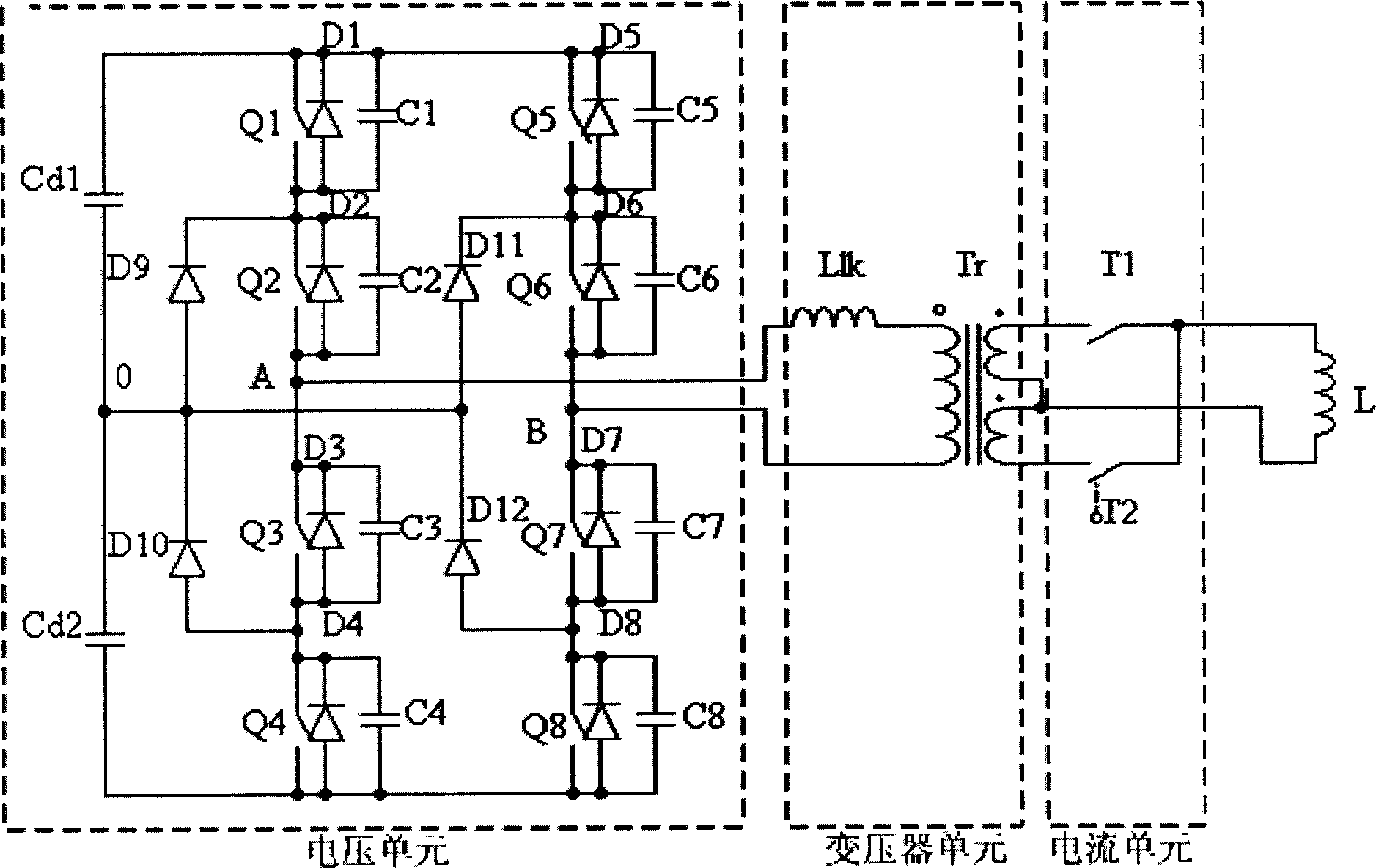
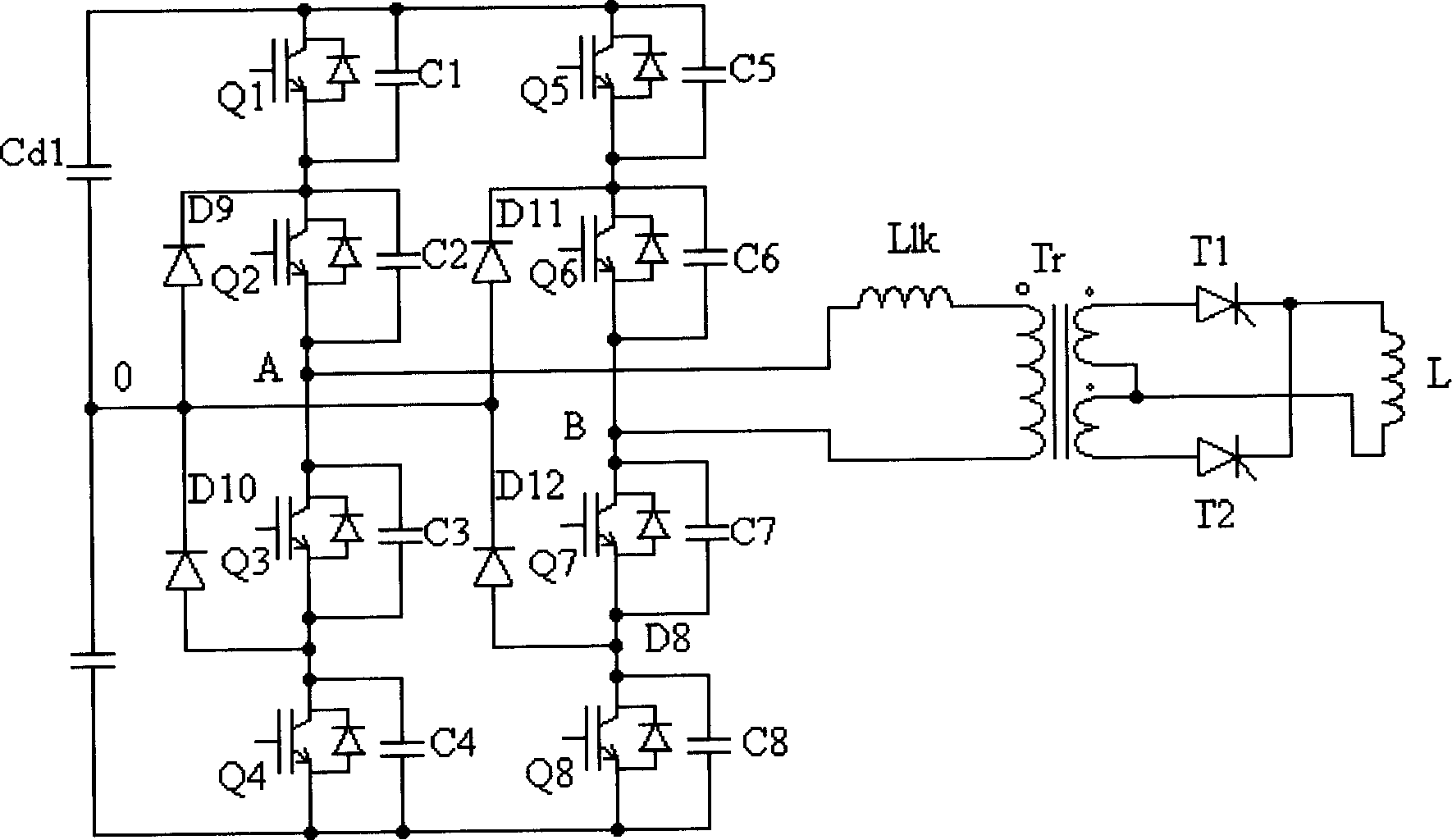
[0016] figure 2 It is a schematic diagram of a typical topology structure of the present invention. It consists of three parts: voltage unit, transformer unit and current unit. Its voltage unit consists of two three-level bridge arms. Switch tubes Q1-Q4 and clamping diodes D9 and D10 form one of the three-level bridge arms. The switch tubes Q1-Q4 are connected end to end, the switch tube Q1 is connected in anti-parallel with the diode D1, and connected in parallel with the capacitor C1; the switch tube Q2 is connected in anti-parallel with the diode D2, and connected in parallel with the capacitor C2; the switch tube Q3 is connected in anti-parallel with the diode D3, and connected in parallel with the capacitor C3 ; The switch tube Q4 is connected in antiparallel with the diode D4 and connected in parallel with the capacitor C4. The midpoints of the switching tubes Q1 and Q2 are connected to the cathode of the clamping diode D9, and the midpoints of the switching tubes Q3...


PUM


Abstract

The dual-way tri-level soft switch DC / DC for superconductance energy-storage comprises a voltage unit composed by two tri-level semi-bridges with midpoint clamping diode, a transformer unit, and a current unit with structure decided by the last unit, total-bridge / semi-bridge current source inverter for common transformer / transformer with middle tap. Wherein, paralleling capacitors on every switch tubes of the semi-bridge, or paralleling not; connecting midpoints of semi-bridge and clamping diode to midpoint of connecting line of two voltage-dividing capacitors. This invention can overcome the unbalance problem of midpoint voltage.

Description

technical field [0001] The invention relates to a DC converter for superconducting energy storage and a control method thereof, in particular to a bidirectional three-level soft switch DC / DC for superconducting energy storage and a control method thereof. Background technique [0002] In recent years, with the development of superconducting material technology, the application of superconducting materials in the field of electric power has attracted more and more attention and attention, and countries all over the world have carried out research on superconducting electric power technology. Among them, superconducting energy storage technology has attracted people's attention because it can realize multiple functions such as pulse energy regulation and power system stability control, and has become the only commercialized superconducting power technology at present. Superconducting energy storage technology is generally divided into two types: voltage source type and current...

Claims


Application Information

Patent Timeline
Patent Type & Authority Applications(China)
IPC IPC(8): H02M3/28H02M3/335
CPCY02B70/10
Inventor 郭文勇赵彩宏欧阳羿辛理夫李学斌
Owner INST OF ELECTRICAL ENG CHINESE ACAD OF SCI
Learn More