Multipart oil wiping ring for pistons of internal combustion engines

An oil scraping ring, multi-part technology, applied in the direction of piston rings, mechanical equipment, engine components, etc., can solve the problem of not being able to know the installation position, etc., to improve oil scraping performance, reduce wear, and increase tangential force Effect

Active Publication Date: 2006-10-11
MAHLE GMBH
View PDF5 Cites 6 Cited by
  • Summary
  • Abstract
  • Description
  • Claims
  • Application Information

AI Technical Summary

Problems solved by technology

However, these embodiments relate only to a single ring, wherein no information is known from these documents regarding the possible installation positions of the multi-part oil wiper ring

Method used


Image

  • Multipart oil wiping ring for pistons of internal combustion engines
  • Multipart oil wiping ring for pistons of internal combustion engines

Examples


Embodiment Construction

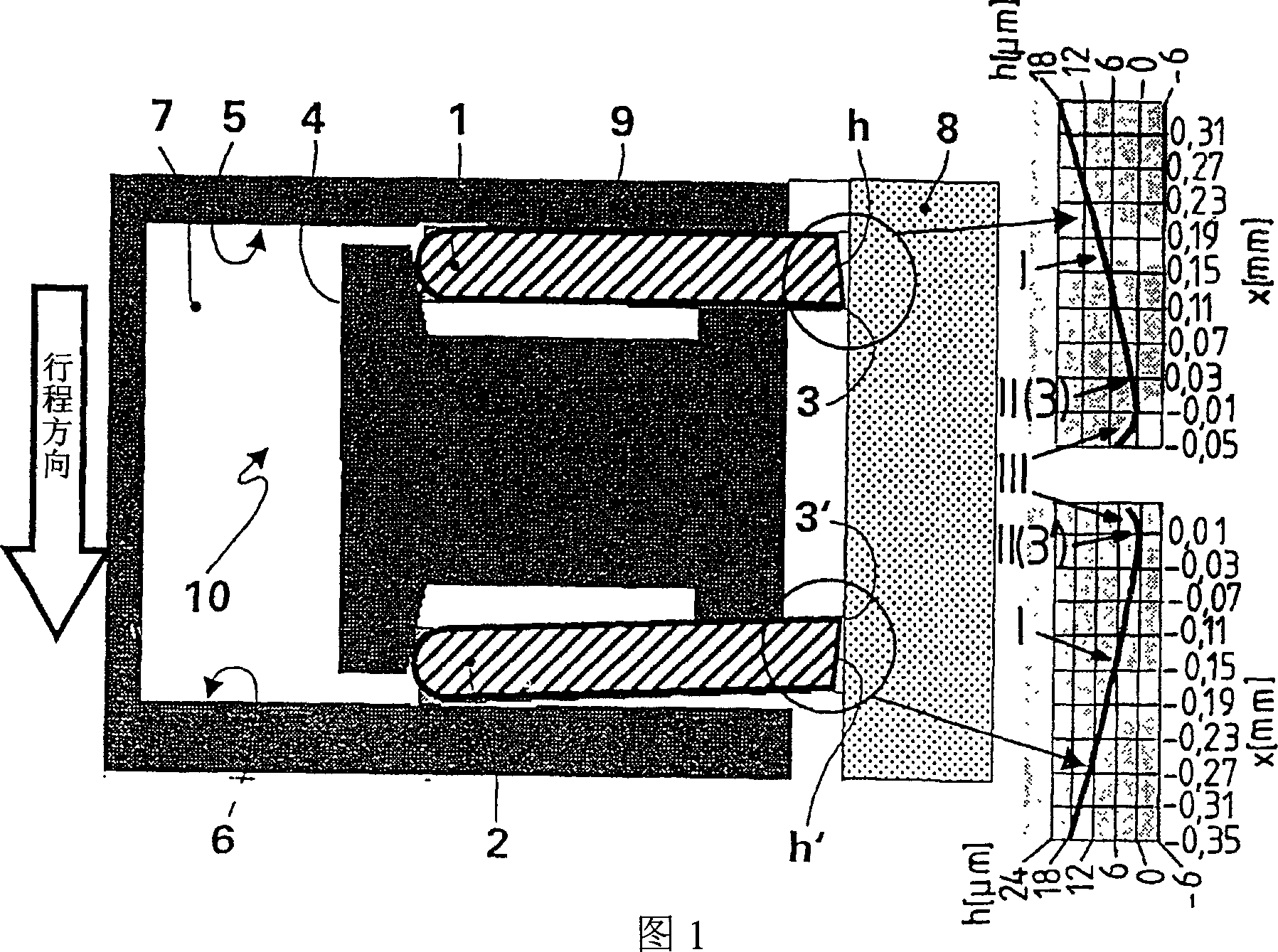
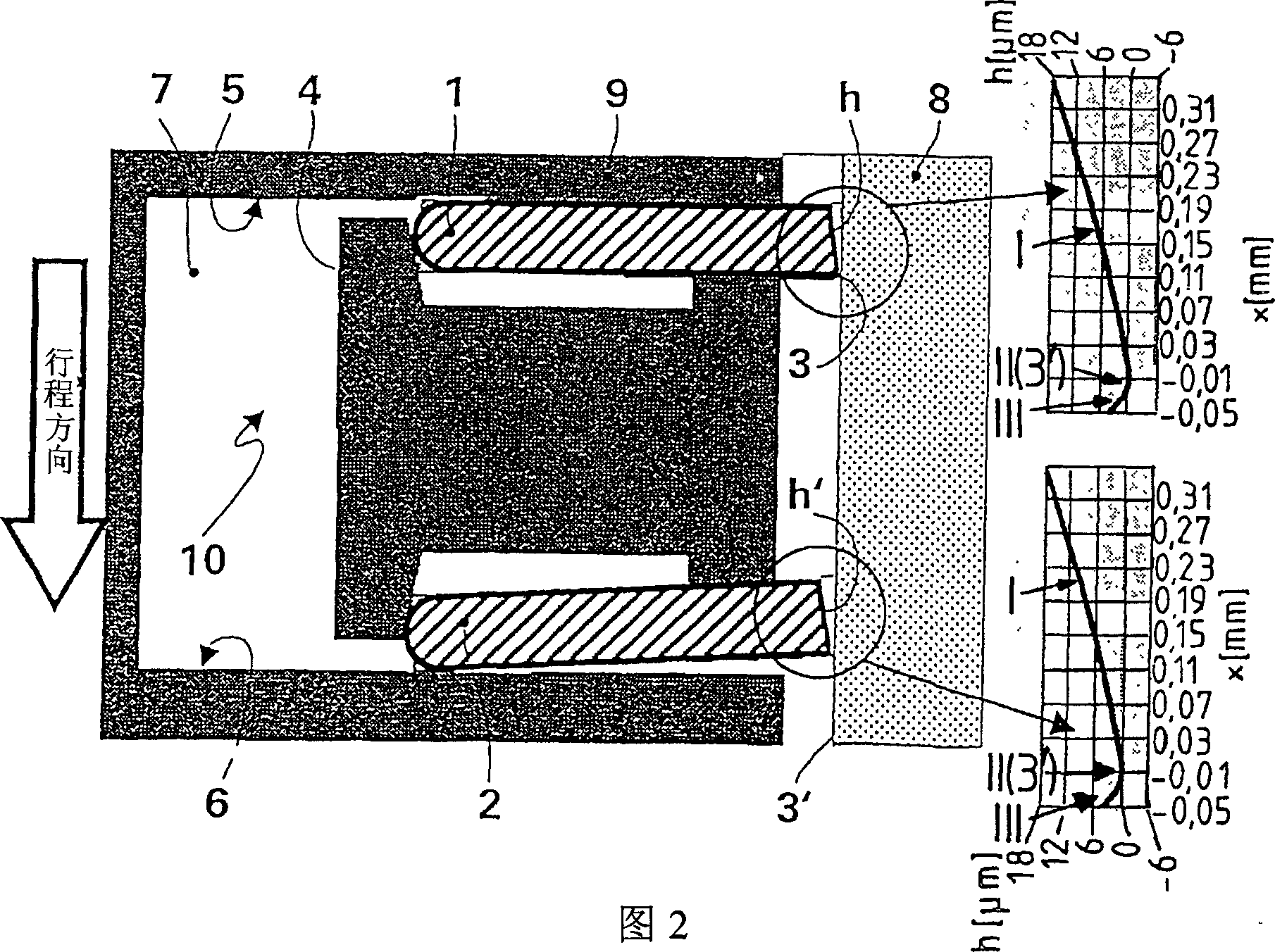
[0026] As can be seen from Figure 1, a multi-part oil wiper ring 10 is composed of two steel strips - discs 1 and 2 and an expansion spring 4, which not only presses the discs axially towards their respective One of the sides 5 and 6 of the annular groove 7 in the piston and presses the disc radially against the cylinder wall 8 . Ring groove side 5 designates the side on the top side of the piston, while ring groove side 6 designates the side facing away from the top side of the piston. According to the invention, the disk 1 has a coronal, asymmetrically shaped working surface h comprising an apex line 3 extending on the periphery of the disk, and the disk 2 has a crowned, asymmetrically shaped working surface h ′, the running surface contains a vertex line 3 ′, wherein each vertex line 3 , 3 ′ serves as an edge in contact with the cylinder wall 8 for scraping oil. In the first exemplary embodiment according to FIG. 1 , the disks 1 and 2 are arranged relative to each other in...


PUM


Abstract

The invention relates to a multipart oil wiping ring for pistons of internal combustion engines, comprising two steel strip-type lamellae with parallel sides, the running surfaces of which are provided with a convexly asymmetric shape having a vertex line that extends across the circumference of the lamellae, and a bracing spring located between the lamellae, said bracing spring pressing the lamellae in an axial direction against one respective side of an annular groove in the piston and in a radial direction against the cylinder wall. The aim of the invention is to obtain an oil-wiping effect that is improved compared to prior art while reducing wear of the running surface. Said aim is achieved by configuring the running surfaces (h, h') of both lamellae so as to make the same correspond to a final contour approaching a condition of wear in the run-in state of the engine, the vertex lines (3, 3') of the running surfaces (h, h') being oriented counter to the direction of the center of the annular groove (3) in the mounted states of the oil ring (10) in the piston.

Description

technical field [0001] The invention relates to a multi-part oil scraper ring for pistons of internal combustion engines, which consists of two steel strip disks with parallel sides, the running surfaces of which each have a crown An asymmetrical shape consisting of a line of vertices extending around the periphery of the discs; and an expansion spring arranged between the discs, which not only axially presses the discs against a respective annular groove in the piston one of the sides and press the disk radially against the cylinder wall. Background technique [0002] Excessive engine oil reaching the combustion chamber, in addition to high fuel consumption, can also have a negative impact on the engine's emissions performance. In order to prevent this phenomenon, a sufficient tangential force of the oil wiper ring for generating a radial contact pressure on the cylinder wall, and thus a good oil scraping action, is indispensable. However, this creates a high surface pres...

Claims


Application Information

Patent Timeline
Patent Type & Authority Applications(China)
IPC IPC(8): F16J9/20F16J9/06
CPCF16J9/206F16J9/066F16J9/00F16J9/06F16J9/20
Inventor 罗尔夫-格哈德·菲德勒
Owner MAHLE GMBH
Why Eureka
Try Eureka