Ultrasonic bone evaluation apparatus

An evaluation device, ultrasonic technology, applied in ultrasonic/sonic/infrasonic Permian technology, ultrasonic/sonic/infrasonic image/data processing, organ motion/change detection, etc. Problems such as the size of the ladder part

Active Publication Date: 2006-10-18
FURUNO ELECTRIC CO LTD
View PDF1 Cites 7 Cited by
  • Summary
  • Abstract
  • Description
  • Claims
  • Application Information

AI Technical Summary

Problems solved by technology

But, in the structure of above-mentioned patent document 1, in order to be able to set the position of foot placement platform in multiple stages, the stepped shape of above-mentioned guide rail just must be formed by multi-stage, must increase the size of step portion, also increases the

Method used


Image

  • Ultrasonic bone evaluation apparatus
  • Ultrasonic bone evaluation apparatus
  • Ultrasonic bone evaluation apparatus

Examples


Embodiment Construction

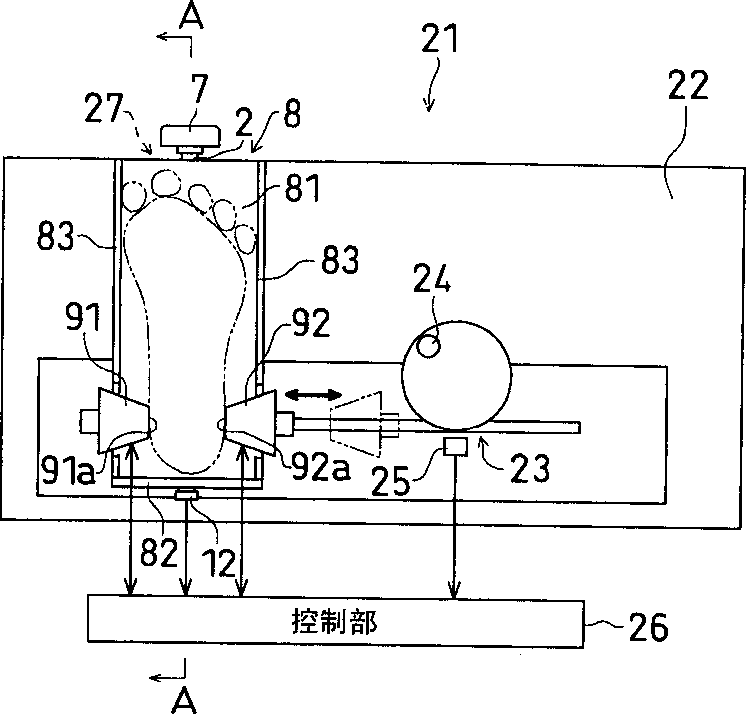
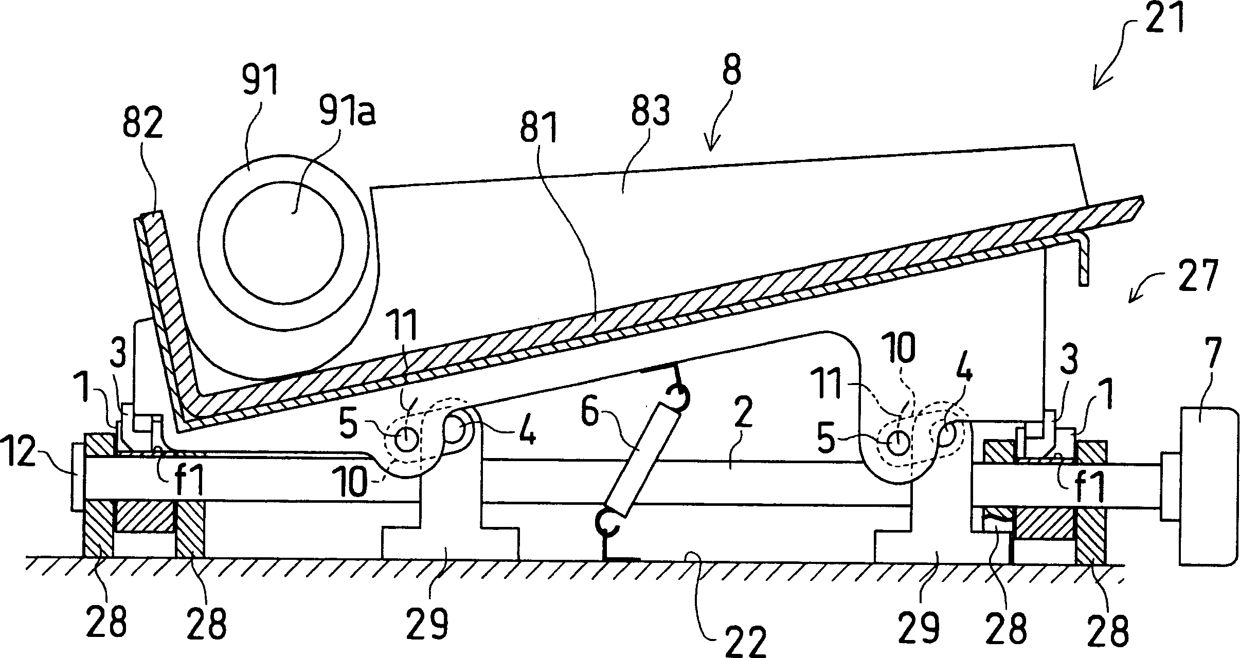
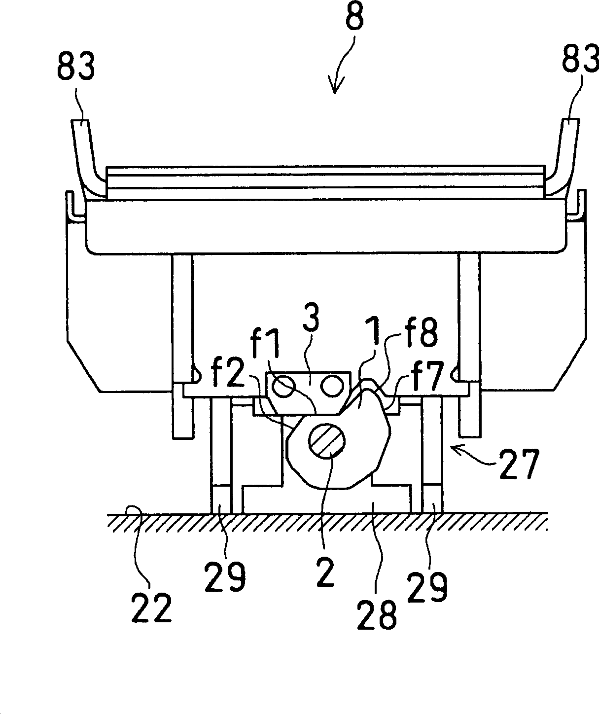
[0038] Next, the bone evaluation device 21 as an embodiment of the invention will be described. figure 1 is a schematic plan view showing the overall configuration of a bone evaluation device according to an embodiment of the present invention; figure 2 yes figure 1 A-A section in the view; image 3 It is a partial cross-sectional view of the bone evaluation device viewed from the front side. Figure 4 Yes indicates operating the rotary dial from figure 2 The side sectional view of the situation that the state makes the foot placement platform rise; Figure 5 is viewed from the front side Figure 4 Partial cross-sectional view of the state bone evaluation device. Figure 6 It is a graph showing an example of the relationship between the detection value of the rotational phase of the cam by the sensor and the height of the footrest which is output.

[0039] as figure 1 The bone evaluation device 21 of the ultrasonic tissue evaluation device shown means that a foot pla...


PUM


Abstract

The present invention provides an ultrasonic bone evaluation device, which performs bone evaluation by sending and receiving ultrasonic waves to the heel. The cam (1) is rotated to change the position. The profile of the rotary cam (1) has a shape with a plurality of R-curved surfaces, wherein the shape is such that the distance between the R-curved surfaces (f1)-(f8) and the center of rotation increases continuously from one side to the other in the direction of the outer circumference. shape. In addition, the rotary cam (1) is arranged to support a substantially central portion in the width direction of the foot resting platform (8) from the lower side. Therefore, the present invention provides a compact configuration that can easily and finely adjust the position of the foot resting table according to the size of the foot.

Description

technical field [0001] The present invention relates to the configuration of an ultrasonic bone evaluation device for evaluating the heel bone by applying ultrasonic waves. Background technique [0002] In recent years, osteoporosis has attracted attention, and the need for bone evaluation is increasing. As a bone evaluation method, the method using X-rays has been the mainstream in the past. However, bone evaluation by ultrasound has the advantages of reducing the size of the device compared with X-rays, and also has the advantage of eliminating X-ray exposure and measuring in a short time. The advantages of less burden on patients, etc., are rapidly spreading recently. [0003] However, the heel bone is often used as a biological evaluation site by the above-mentioned device, but the shape and size of the heel bone vary among individuals, and the optimal measurement point of the calcaneus varies from person to person. In particular, there is a considerable difference in ...

Claims


Application Information

Patent Timeline
IPC IPC(8): A61B8/08
Inventor 田原忠新井龙雄
Owner FURUNO ELECTRIC CO LTD
Why Eureka
Try Eureka