

Composite grate plate for automatic mill
A composite lattice and autogenous mill technology, applied in grain processing and other directions, can solve the problems of product pollution, increased production cost, and high price.
- Summary
- Abstract
- Description
- Claims
- Application Information
AI Technical Summary
Problems solved by technology
Method used
Image

Examples
Embodiment Construction
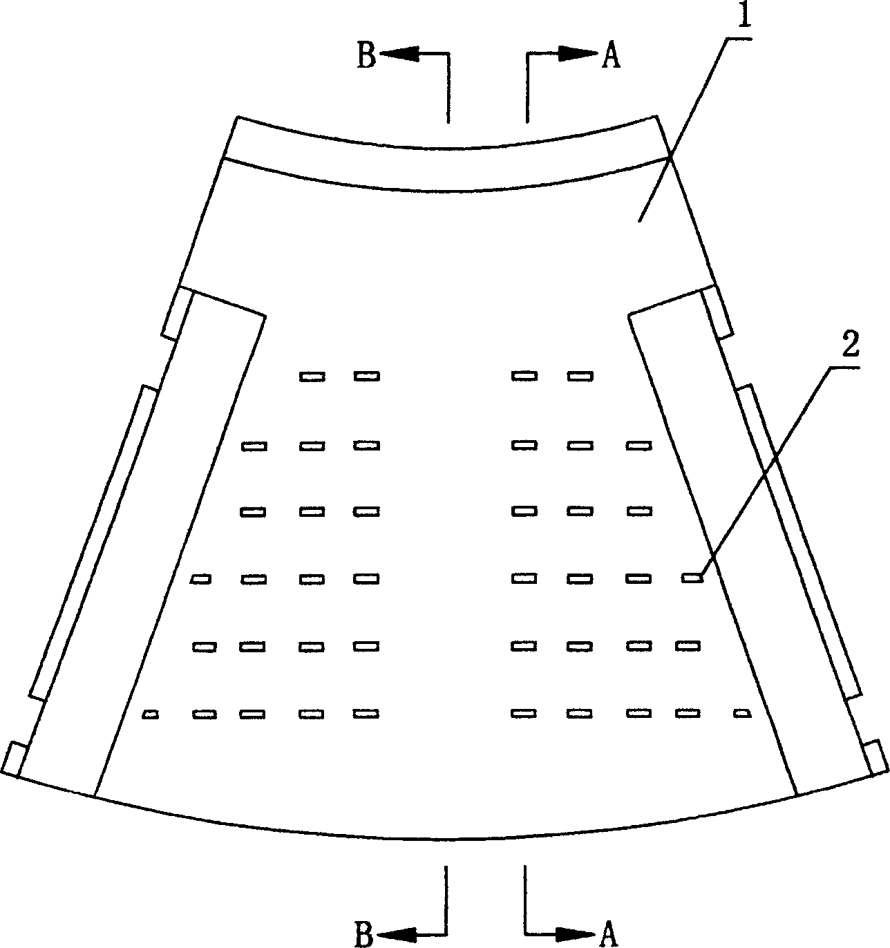
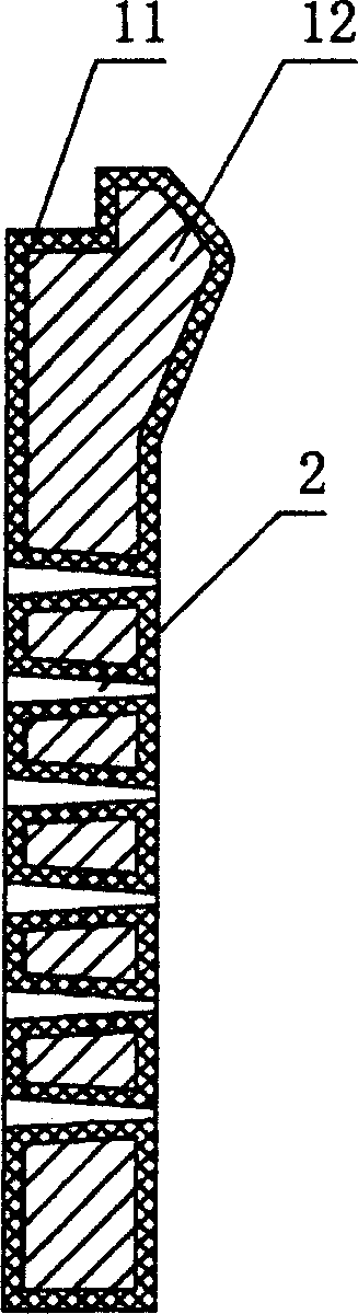
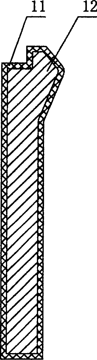
[0017] Refer to Figure 4 In the figure, the grating plate 7 currently used is installed at the discharge end of the grinding cylinder 3 of the self-milling machine. The grating plate 7 is arranged in the circumferential direction of the grinding cylinder 3 to divide the grinding cylinder 3 into a material self-grinding space and row. In the discharging space, there are several dustpan plates 4 arranged along the circumference of the grinding cylinder 3 that can transport the quartz sand particles screened by the grating plate 7 to the discharge cylinder 5, because the grating plates currently used by people Most of the discharge holes are strip-shaped holes. There are some larger quartz sand particles in the quartz sand screened by the grid plate with strip-shaped discharge holes, so there is a self-returning screen in the discharge barrel 5. 6. The self-returning sieve 6 can transport the larger quartz sand particles back to the grinding cylinder 3 for self-grinding, while the s...
PUM
 Abstract
Description
Claims
Application Information