Energy-saving speeding and boosting mechanism and method

A speed-increasing mechanism and force-increasing technology, which is applied in the direction of mechanical equipment, gear transmission, belt/chain/gear, etc., can solve problems such as power loss, and achieve the effect of speed increase and high mechanical conversion efficiency

Inactive Publication Date: 2006-10-18
王红军
View PDF0 Cites 1 Cited by
  • Summary
  • Abstract
  • Description
  • Claims
  • Application Information

AI Technical Summary

Problems solved by technology

Its disadvantages: when the power on the power source shaft is transmitted to the machine through the pulley or gear, due to the large diameter of the pulley or gear (much larger than the diameter of the power shaft), it will inevitably cause a loss of part of the power , the degree of loss can be calculated from the diameter of the pulley or gear and the diameter of the power shaft: the larger the diameter of the pulley or gear, the greater the force loss

Method used


Image

  • Energy-saving speeding and boosting mechanism and method
  • Energy-saving speeding and boosting mechanism and method

Examples


Embodiment 1

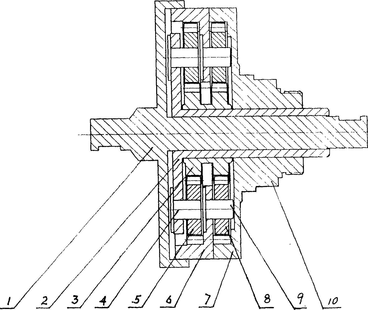
[0014] Embodiment 1: with reference to attached figure 1 . In the energy-saving power-increasing speed-up mechanism, the input shaft 1 is in the structure of a central shaft cover, and the shaft and the cover are connected as one or in an integral structure. The planetary carrier 2 has a T-shaped sleeve flange structure (that is, a flange sleeve structure---a circular cover with a middle hole is connected to the end of the sleeve). The planetary carrier 2 is sleeved on the shaft-in shaft 1, and the sun gear 3 is a double-wheel conjoined structure and is processed and manufactured by using the prior art. The sun gear 3 is set on the planetary carrier 2, the planetary gear 5 is connected with the planetary carrier through the mandrel 4 and the planetary gear 5 meshes with the sun gear 3, and the inner gear 6 is set on the sun gear, and the internal teeth of the inner gear mesh with the planetary gear 5 1. The outer wall of the inner gear is connected with the inner wall of the...

Embodiment 2

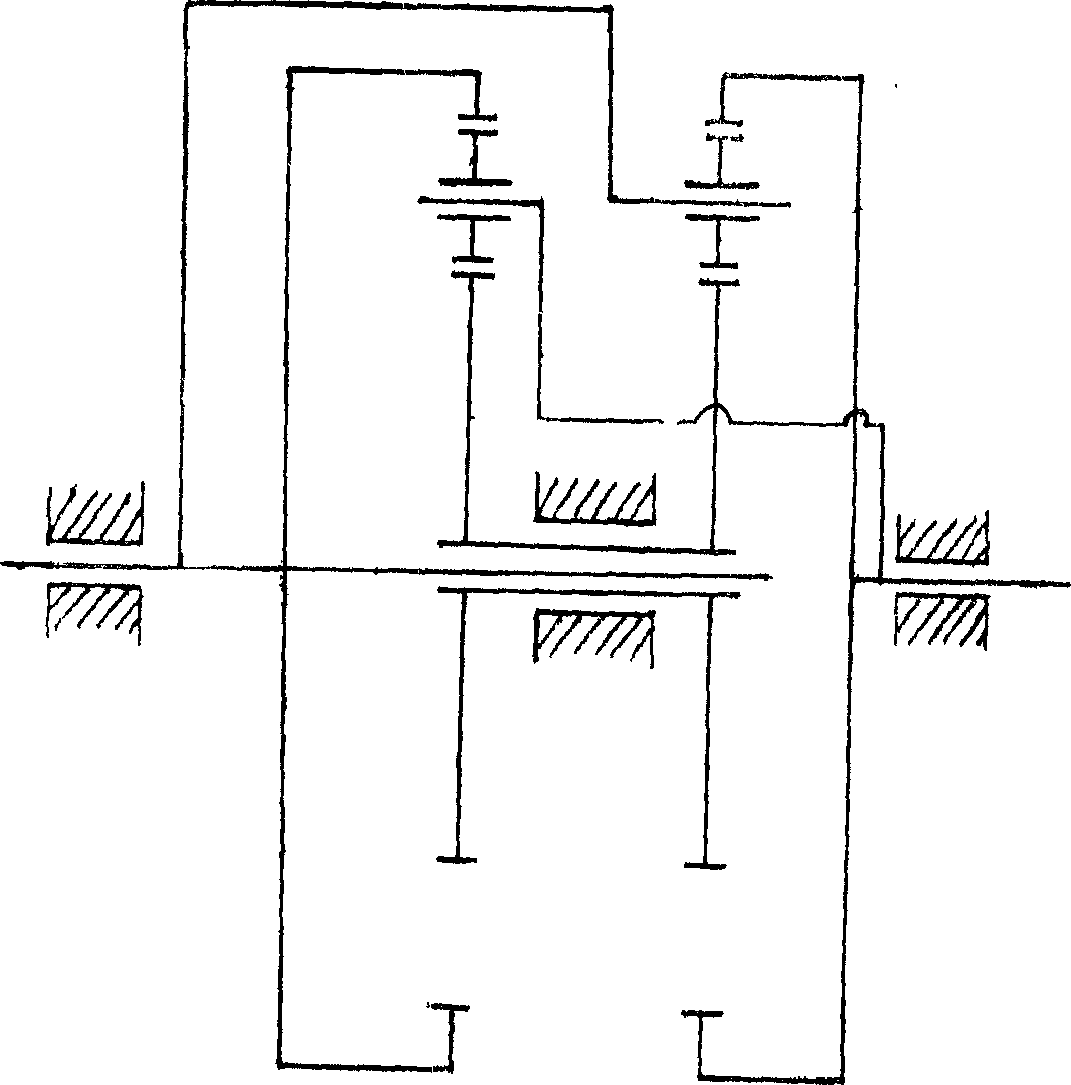
[0016] Embodiment 2: energy-saving and power-increasing speed-up method, the power on the input shaft is transmitted in two ways, one way is directly transmitted to the output shaft through the star gear set on the rotating arm and the output shaft, and the other way is passed through the star gear on the input shaft The star gear set on the group and the output shaft is transmitted to the output shaft.


PUM


Abstract

The present invention relates to one kind of power transferring speeding and boosting mechanism and method. The power transferring speeding and boosting mechanism includes planet carrier around the input shaft, sun gear around the planet carrier, planet gear connected to the planet carrier via mandril and meshed to the sun gear, annular gear around the sun gear meshed to the planet gear and with outer wall connected to the input shaft, output annular gear connected to the planet carrier and meshed to the planet gear, and output shaft integrated with the output annular gear. The present invention has the advantages of doubled output speed, and high mechanical conversion efficiency.

Description

Technical field: [0001] The invention relates to a power transmission booster mechanism and a force booster method, belonging to the field of power transmission mechanism manufacturing. Background technique: [0002] In the existing power transmission mechanism, a wheel disc (such as a belt pulley, a gear) is generally installed on the bearing of the power source, and then the machine shaft is driven by the belt wheel or gear to work. Its disadvantages: when the power on the power source shaft is transmitted to the machine through the pulley or gear, due to the large diameter of the pulley or gear (much larger than the diameter of the power shaft), it will inevitably cause a loss of part of the power , the degree of loss is calculated from the diameter of the pulley or gear and the diameter of the power shaft: the larger the diameter of the pulley or gear, the greater the loss of force. Invention content: [0003] Design purpose: To avoid the deficiencies in the backgroun...

Claims


Application Information

Patent Timeline
Patent Type & Authority Applications(China)
IPC IPC(8): F16H1/28
Inventor 王红军
Owner 王红军
Why Eureka
Try Eureka