Display unit, drive method for display unit, electronic apparatus mounting display unit thereon

A display device and driver technology, applied in static indicators, instruments, nonlinear optics, etc., can solve problems such as difficult to realize, unable to display natural images, unable to take into account low power consumption and high display quality, etc., to achieve low power consumption Effect

Inactive Publication Date: 2006-10-18
SHARP KK
View PDF5 Cites 16 Cited by
  • Summary
  • Abstract
  • Description
  • Claims
  • Application Information

AI Technical Summary

Problems solved by technology

Therefore, there is a disadvantage of increasing the cost due to the increase in the size of the peripheral circuit
[0023] In the method disclosed in Japanese Patent Application Laid-Open No. 6-342148, since the ferroelectric liquid crystal is basically a value (black and white) display, color tone display cannot be performed, and natural images cannot be displayed. Requires advanced plate making technology, so it is difficult to realize, and has not been put into practical use so far
[0024] In this way, the existing driving methods for matrix liquid crystal display devices cannot easily achieve sub-low power consumption while satisfying basic display qualities such as brightness, contrast, response speed, and gray scale.
Moreover, the above-mentioned existing matrix-type liquid crystal display device activation method cannot take into account sufficient low power consumption and flicker-free high display quality.

Method used


Image

  • Display unit, drive method for display unit, electronic apparatus mounting display unit thereon
  • Display unit, drive method for display unit, electronic apparatus mounting display unit thereon
  • Display unit, drive method for display unit, electronic apparatus mounting display unit thereon

Examples


Embodiment Construction

[0098] The best way to implement the invention

[0099] Embodiment 1

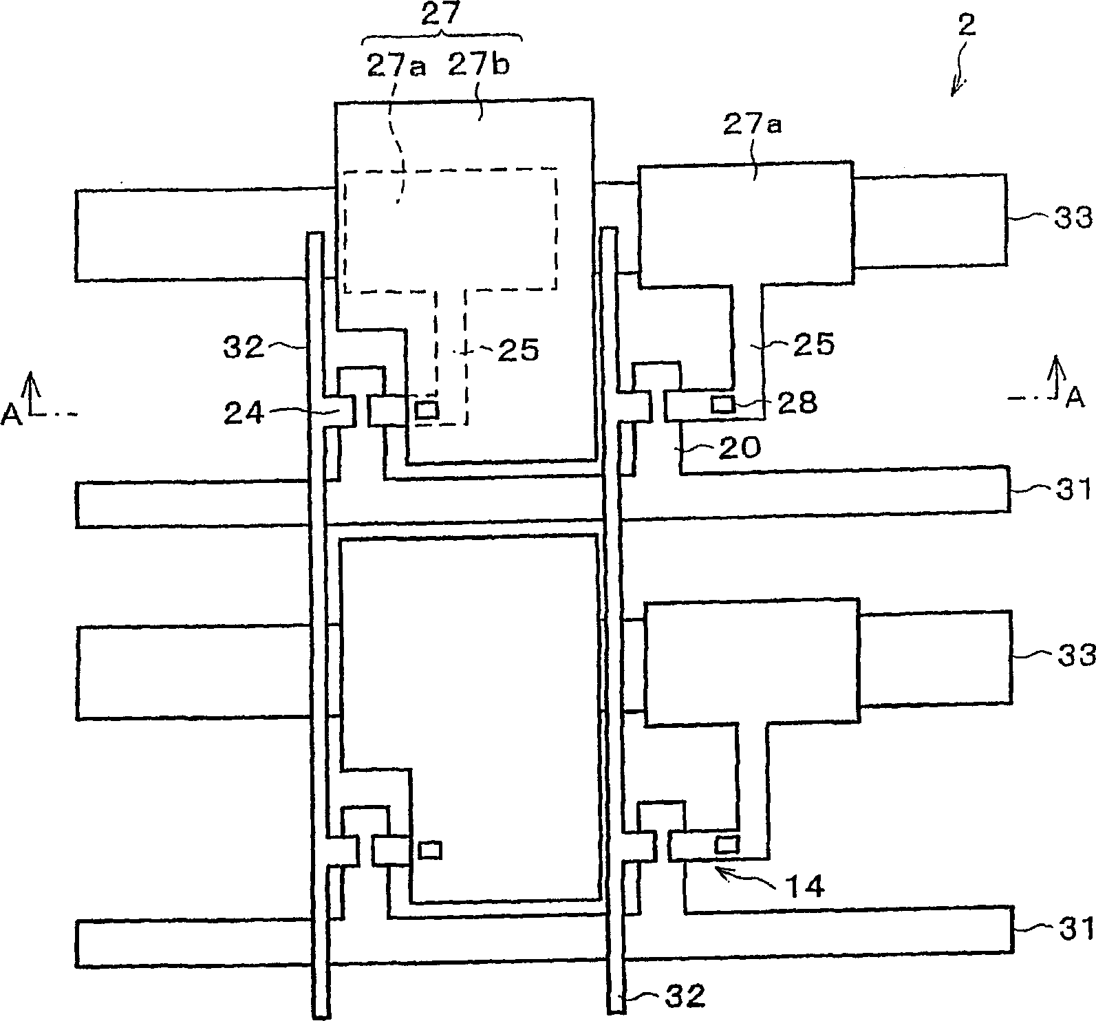
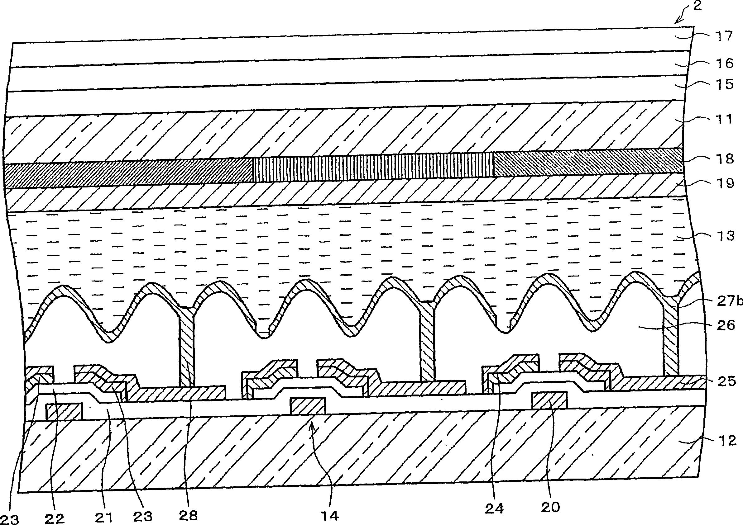
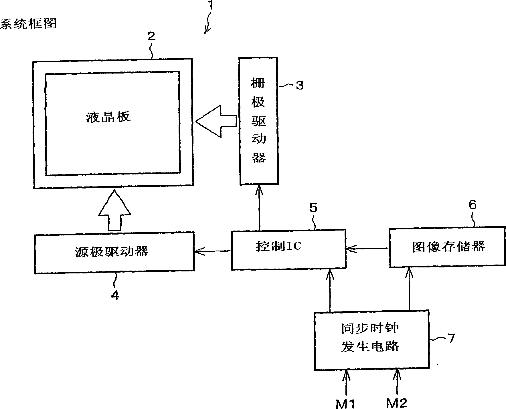
[0100] according to Figure 1 to Figure 1 1 Description The display device according to an embodiment of the present invention is as follows.

[0101] First of all, according to the investigation of the applicant in this case, it is found that when the rewriting frequency is set to a low frequency below 30 Hz to drive the liquid crystal display device with the on-gate Cs structure, the reasons for the display flicker are as follows.

[0102] In a liquid crystal display element with an active element, when the auxiliary capacitor electrode of the pixel is formed on the scanning signal line above the pixel in the "at gate Cs" condition, the scanning signal is applied to the scanning signal line above the line At this time, the pixel electrode potential of the pixel varies greatly. Generally, when the rewriting frequency is above 30 Hz, the response of the liquid crystal molecules caused by the change of the pixel...


PUM


Abstract

A liquid crystal panel ( 2 ) includes scanning signal lines ( 31 ) for supplying scanning signals to gate electrodes ( 20 ) of TFTs ( 14 ), and data signal lines ( 32 ) for supplying data signals to data electrodes ( 24 ) of TFTs. The liquid crystal panel further includes auxiliary capacitive electrode pads ( 27 a) for use in forming auxiliary capacitance and an auxiliary capacitive lines ( 33 ) so as not to generate a capacitive bond with the scanning signal lines. The liquid crystal panel is driven at a rewriting frequency of a screen of not more than 30 Hz. As a result, the liquid crystal panel can be driven at a low consumption power while maintaining a desirable display quality of the liquid crystal panel.

Description

[0001] This application is a divisional application of the invention patent application filed by the applicant on April 24, 2001 with the application number "01812023.7" and the invention title "display device, display device driving method and electronic equipment equipped with display device" . Technical field [0002] The present invention relates to low power consumption of display devices. Background technique [0003] In recent years, the application of liquid crystal display devices in word processors, laptop personal computers, pocket TVs, etc. has been rapidly developed. Especially in the liquid crystal display device, the reflective liquid crystal display device that performs display by reflecting external incident light does not require a backlight, consumes less power, is thin, and can be reduced in weight, which is eye-catching. [0004] Existing reflective liquid crystal display devices can be roughly divided into: pen-segment display methods that can only display si...

Claims


Application Information

Patent Timeline
Patent Type & Authority Applications(China)
IPC IPC(8): G02F1/133G02F1/1368G09G3/36
Inventor 津田和彦清水雅宏中村久和熊田浩二太田隆滋亀崎豐
Owner SHARP KK
Why Eureka
Try Eureka