Magnetic approach switch

A technology of magnetic proximity switch and magnetic body, applied in the direction of magnetic switch, magnetic/electric field switch, electric switch, etc., can solve problems such as not shown

Inactive Publication Date: 2006-10-18
FUJI ELECTRIC FA COMPONENTS & SYST CO LTD
View PDF0 Cites 6 Cited by
  • Summary
  • Abstract
  • Description
  • Claims
  • Application Information

AI Technical Summary

Problems solved by technology

Although in fact there are lines of magnetic force 212 and lines of equal magnetic force 123 below the X-axis, but in Figure 10 lines 212 and 123 below the x-axis are not shown in the

Method used


Image

  • Magnetic approach switch
  • Magnetic approach switch
  • Magnetic approach switch

Examples


no. 1 example 〕

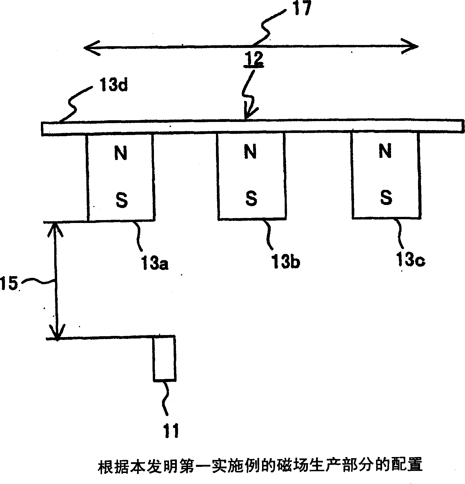
[0063] figure 2 is a block diagram of the magnetic field generating section 12 according to the first embodiment of the present invention.

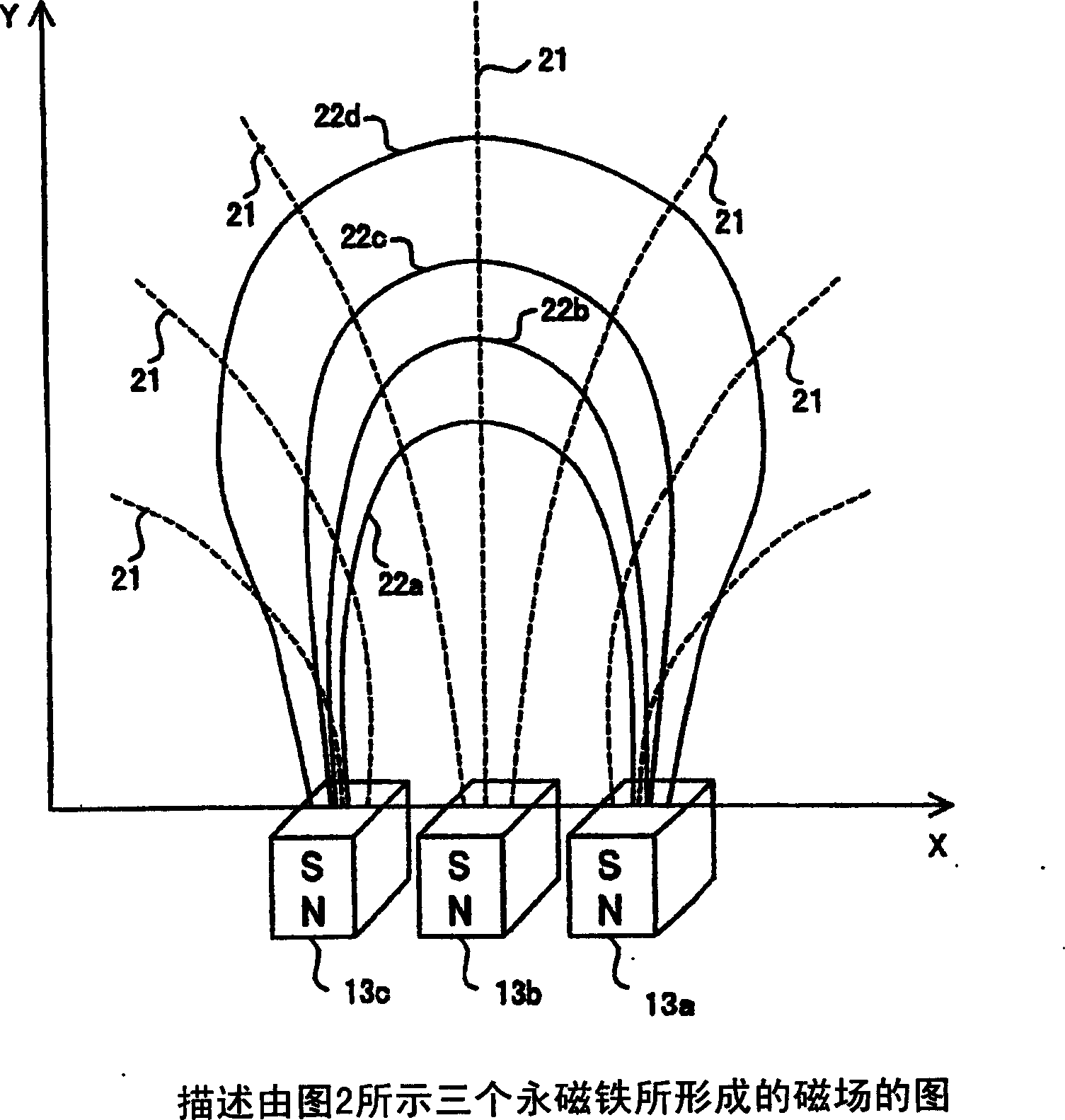
[0064] figure 2 The illustrated magnetic field generating portion 12 includes three permanent magnets 13 (13a, 13b, 13c) and a magnetic metal material 13d attached to these permanent magnets by its magnetic force. The permanent magnets 13 a , 13 b and 13 c are arranged so that their S poles face the magnetic field detecting portion 11 . A plate-like magnetic metal material 13d is attached and placed on the N pole faces of the permanent magnets 13a, 13b and 13c.

[0065] The plate-like magnetic metal material 13d preferably exhibits a high degree of magnetic permeability so that magnetic lines of force can easily pass through, a high saturation magnetic flux density and a small hysteresis. The plate-shaped magnetic metal material 13d can not only be used as a fixed arrangement of the permanent magnets 13a to 13c, but also guide the fl...

no. 2 example

[0090] Image 6 is a diagram of the arrangement of the permanent magnets of the magnetic field generating section according to the second embodiment of the present invention.

[0091] Such as Image 6 The illustrated magnetic field generating section 12 includes five permanent magnets 13 - 1 to 13 - 5 , a housing 50 and a sealant 60 .

[0092] The housing 50 includes five grooves in which the upper portions of the respective permanent magnets 13-1 to 13-5 are installed. Such as Figure 5 As shown, these grooves are arranged at similar intervals, in which the permanent magnets 13-1 to 13-5 are arranged in parallel to each other. The permanent magnets 13-1 to 13-5 installed in the respective grooves are fixed with a sealant 60 surrounding the lower portions of the permanent magnets 13-1 to 13-5.

[0093] The case 50 and the sealant 60 must be non-magnetic so as not to block the magnetic flux generated from the permanent magnets 13-1 to 13-5. The relative magnetic permeabili...


PUM


Abstract

PROBLEM TO BE SOLVED: To reduce a change of an active position on gap fluctuation between a magnetic field detecting part and a magnetic field generating part of a magnetic proximity switch.

SOLUTION: The magnetic field generating part 12 comprises a plate shaped magnetic metal body 13d, three permanent magnets 13a, 13b, 13c having a same shape and material and attracted by the magnetic metal body 13d. The three permanent magnets 13a-13c are arranged in parallel at an equal interval along a sliding direction of the magnetic field generating part 12 so that a pole face of an equal pole (an S pole) are going to face to the magnetic field detecting part 11. An isodynamic line linking points having a same gap directional component of magnetic force generated by the respective permanent magnets 13a-13c makes a curved line with a small change in the active position on the fluctuation of the gap direction on both sides.

COPYRIGHT: (C)2007,JPO&INPIT

Description

technical field [0001] The invention relates to a magnetic proximity switch, which includes a magnetic field generating part that can generate a magnetic field, and a magnetic field detecting part that slides relative to the magnetic field generating part and detects the magnetic field generated in the magnetic field generating part. Background technique [0002] A magnetic proximity switch is known for stopping and controlling an elevator car at each floor. [0003] [Publicly known example 1] [0004] Figure 7 is a block diagram showing the overall configuration of a first conventional magnetic proximity switch according to Known Example 1. [0005] refer to Figure 7 , the first conventional magnetic proximity switch 100 includes a magnetic detector element (magnetic field detection section) 101 and a working magnet (magnetic field generation section) 103 . The magnetic detection element 101 is a magnetoresistive element or a hole element. The working magnet 103 is a p...

Claims


Application Information

Patent Timeline
Patent Type & Authority Applications(China)
IPC IPC(8): H01H36/00
CPCH01H36/00H01H36/0073H01H2239/074
Inventor 冈本毅
Owner FUJI ELECTRIC FA COMPONENTS & SYST CO LTD
Why Eureka
Try Eureka