
Battery controller

A technology of battery controller and secondary battery, which is applied in current collectors, battery circuit devices, circuit monitoring/indication, etc. It can solve problems such as shortening unit life, achieve the effect of reducing capacity and strengthening data backup functions

Inactive Publication Date: 2006-10-18
SHIN KOBE ELECTRIC MASCH CO LTD
View PDF2 Cites 3 Cited by
  • Summary
  • Abstract
  • Description
  • Claims
  • Application Information

AI Technical Summary

Problems solved by technology

[0007] thus shortening the life of the unit

Method used


Image

  • Battery controller
  • Battery controller
  • Battery controller

Examples


Embodiment approach 1

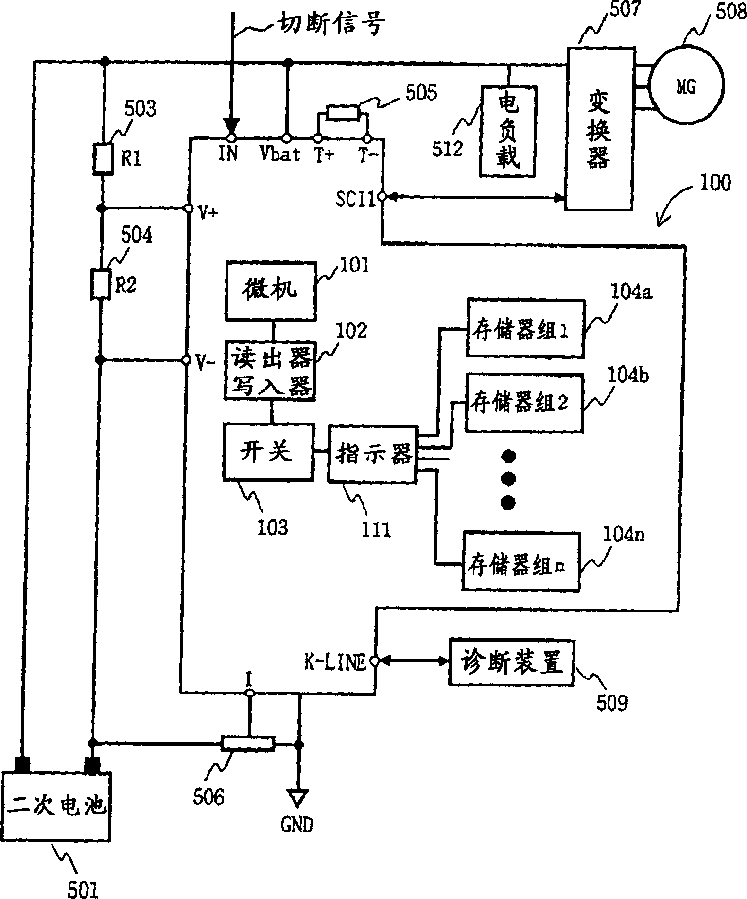
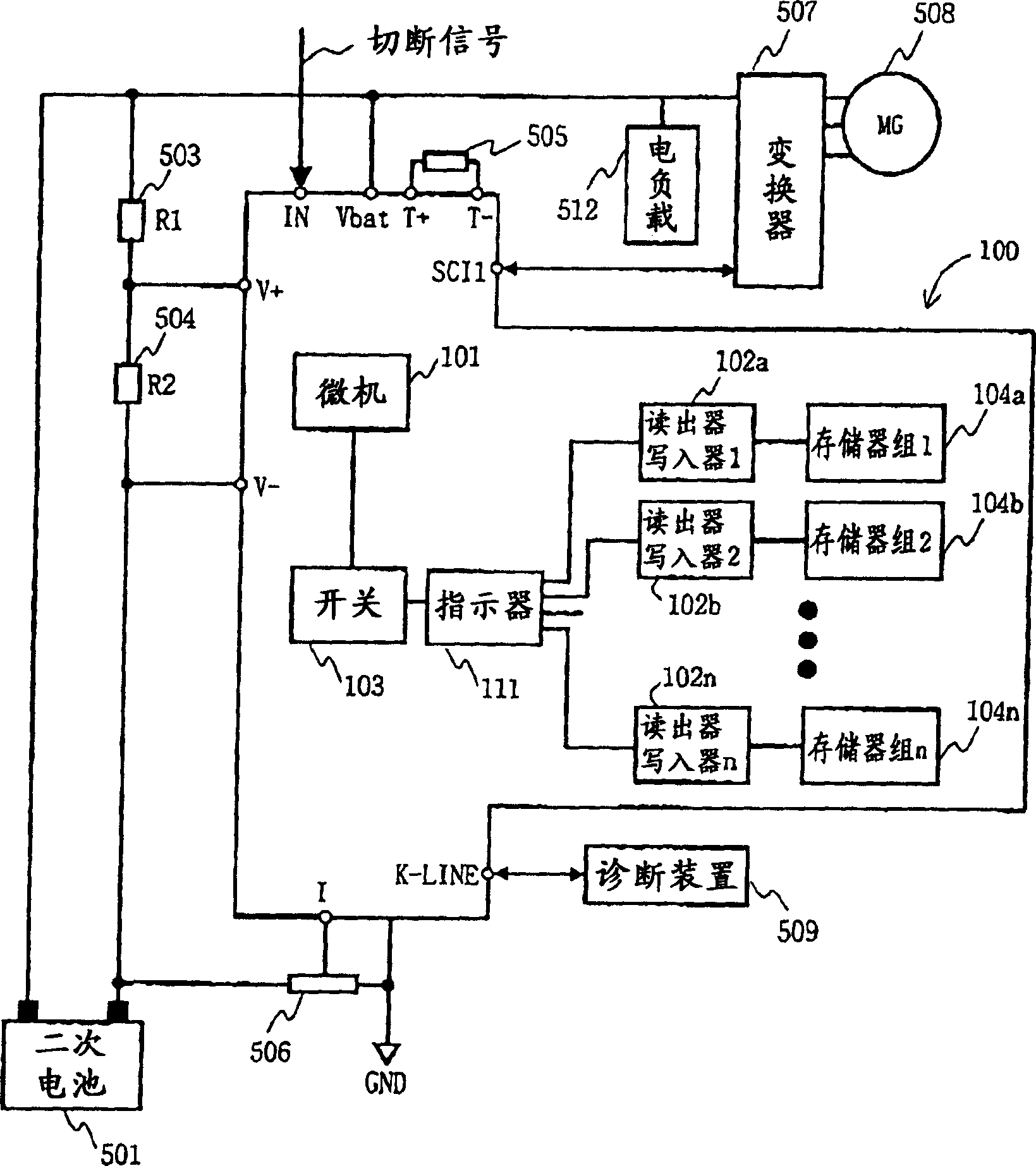
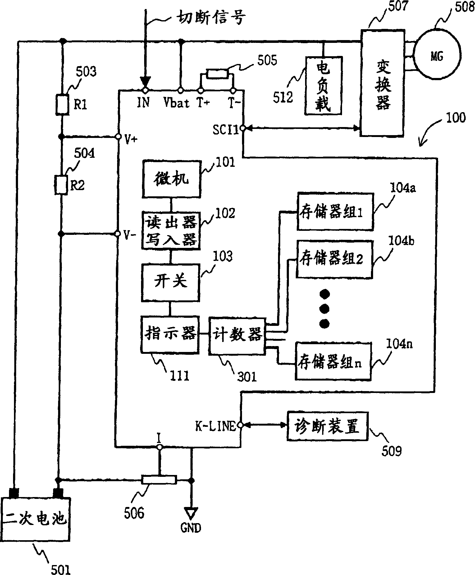
[0030] The electric power system includes a secondary battery 501 as a power source, a motor generator 508 controlled to supply power through an inverter 507 , and a battery controller 100 that monitors the state of the secondary battery 501 and the like. In addition, there are electric loads 512 such as lamps and heaters that use the secondary battery 501 as a power source.

[0031] The electric motor 508 is coupled with an unillustrated wheel to drive the wheel.

[0032] The inverter 507 converts the DC power of the secondary battery 501 into AC power to drive the electric motor 508 . Inverter 507 converts AC power generated by motor generator 508 into DC power, and inputs it to secondary battery 501 .

[0033] A secondary battery (battery power supply) 501 serving as an on-vehicle power supply is a rechargeable battery such as a lead battery, a lithium secondary battery, a nickel hydrogen battery, or an electric double layer capacitor. The secondary battery 501 is connect...


PUM


Abstract

To provide a battery controller that can ensure the required number of rewriting times without replacing a memory. A plurality of memory banks (104a-104n) rewritable in one unit or in multiple units are provided, and the memory banks (104a-104n) are switched and used by a switch (103). A reader / writer (102) for writing or reading data to or from memory banks (104a to 104n) is provided, and a switch (103) sequentially switches memory banks to be rewritten each time switching is performed.

Description

technical field [0001] The present invention relates to a battery controller, in particular to a battery controller for detecting and controlling the state of electric storage devices such as lead batteries, lithium batteries, nickel-metal hydride batteries, and electric double-layer capacitors. Background technique [0002] In power supply units that use power storage devices such as batteries, distributed power storage devices, and electric vehicles, battery controllers that detect the state of the power storage devices and control the power storage devices are used in order to use the power storage devices safely and efficiently. The state of the so-called power storage device includes: the state of charge (the first letter of State Of Charge, called SOC) or remaining capacity indicating the degree of charging, or how much remaining electric energy can be discharged, or the remaining capacity, and indicating the deterioration or weakening to what extent. Degree of health ...

Claims


Application Information

Patent Timeline
Patent Type & Authority Applications(China)
IPC IPC(8): H02J7/00
CPCG01R31/006G01R31/3648G01R31/392G01R31/379G01R31/371H02J7/0048H02J7/005
Inventor 江守昭彦河原洋平高桥广考村林文夫平沢今吉大越哲郎
Owner SHIN KOBE ELECTRIC MASCH CO LTD
Learn More