Rotaryshaft gas-supply rotor engine

A technology of a rotary engine and a rotating shaft, which is applied to machines/engines, mechanisms that generate mechanical power, and mechanical equipment, etc., can solve problems such as fuel consumption, pollution, and complex structural design.

Inactive Publication Date: 2006-10-25
李晓东
View PDF0 Cites 26 Cited by
  • Summary
  • Abstract
  • Description
  • Claims
  • Application Information

AI Technical Summary

Problems solved by technology

[0002] There are many types of engines in the prior art. Taking internal combustion engines as an example, no matter whether they are rotary or piston engines, there is a problem

Method used


Image

  • Rotaryshaft gas-supply rotor engine
  • Rotaryshaft gas-supply rotor engine
  • Rotaryshaft gas-supply rotor engine

Examples


Embodiment Construction

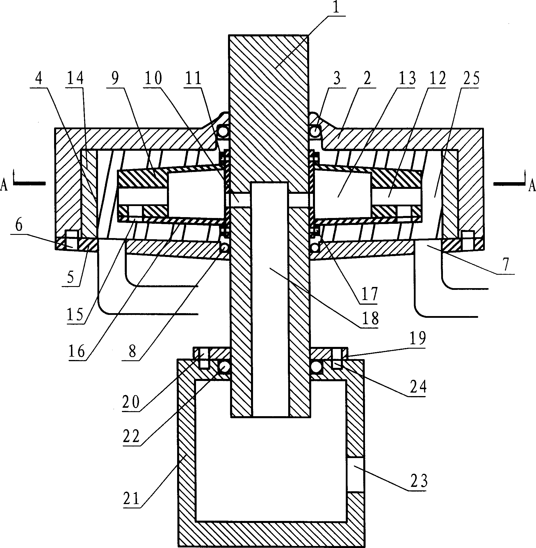
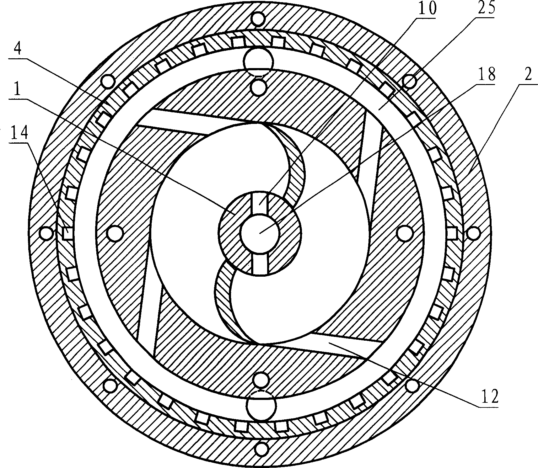
[0012] Referring to accompanying drawing: in the embodiment that accompanying drawing provides, the concrete technical scheme that the present invention adopts is as follows:

[0013] The rotary shaft gas supply rotor engine includes a rotary shaft 1 and an air supply cabin 21; wherein: the rotary shaft has an axial air intake channel 18 and a radial air guide hole 10 communicating with the gas supply cabin, and the rotary shaft is installed on the stator through a sealed bearing seat 3 In the air chamber, there is a rotor air chamber 13 fixed to the rotating shaft in the stator air chamber 25, and the rotor air chamber has an air inlet to communicate with the radial air guide hole, and the rotor air chamber has air nozzles distributed in the same tangential direction; The chamber has an exhaust hole 7 communicating with the exhaust chamber.

[0014] In the embodiment shown in the drawings, in order to facilitate processing, the rotor air chamber 13 is composed of the fixed co...


PUM


Abstract

The invention relates to rotating shaft air feed rotary piston machine. It includes rotating shaft and air feed cabin. And the rotating shaft is set axial air induction channel and radial air induction hole. And it is set in stator air chamber by sealed bearing seat. The stator air chamber is set rotator air chamber. It is set intake hole connected to radial air induction hole. The stator air chamber is set air nozzle. The rotator is set exhaust hole. It has the advantages of energy saving, safe, long useful life, economic, and environment protecting.

Description

technical field [0001] The invention relates to a power device, which is a device that uses compressed gas, steam or water energy as an energy source to drive a rotor to rotate to generate power. Specifically, it is a device that uses a rotating shaft as a channel for providing energy to drive the rotor to rotate to generate power. Background technique [0002] There are many types of engines in the prior art. Taking an internal combustion engine as an example, no matter whether it is a rotary or piston engine, there is a problem that combustion needs to consume fuel and generate pollution. In order to reduce energy consumption and pollution emissions, its structural design is becoming more and more complex. Contents of the invention [0003] The purpose of the present invention is to provide a rotating shaft air-supply rotary engine powered by compressed air, which has simple structure, high efficiency and low energy consumption and has practical application significance....

Claims


Application Information

Patent Timeline
IPC IPC(8): F03G7/00
Inventor 李晓东
Owner 李晓东
Why Eureka
Try Eureka