Safety throttle valve

A throttle valve and safety technology, which is applied in the direction of the valve device, the cock including the cut-off device, the engine components, etc., can solve the problem of frying the tank and achieve the effect of ensuring the safety of the system

Inactive Publication Date: 2006-10-25
JIANGSU GUOLI FORGING MACHINE TOOL
View PDF0 Cites 0 Cited by
  • Summary
  • Abstract
  • Description
  • Claims
  • Application Information

AI Technical Summary

Problems solved by technology

If this kind of throttle valve is installed in the hydraulic system of the bending machine, when the valve core is adjusted to the closed state, the valve 12 will not work as a safety valve, and it cannot drain oil to the oil tank. Valve 8, valve 9, valve 10 When any one of them breaks down, the l

Method used


Image

  • Safety throttle valve
  • Safety throttle valve
  • Safety throttle valve

Examples


Example Embodiment

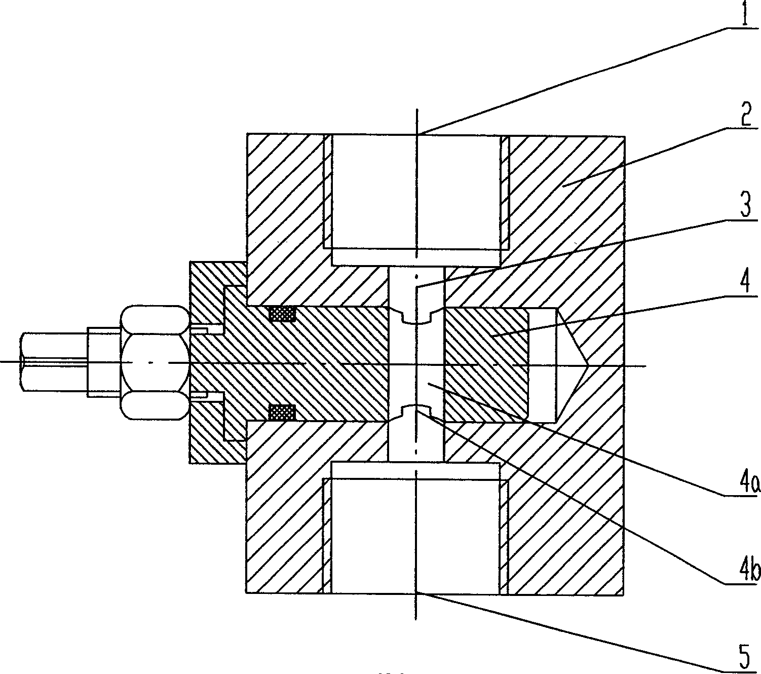
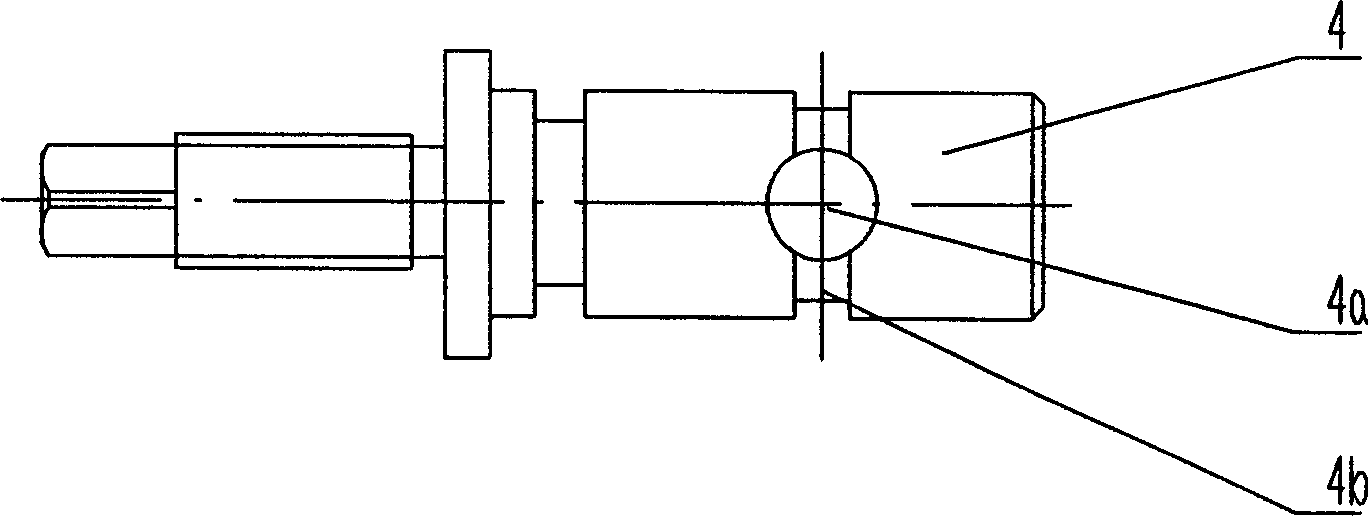
[0009] As shown in the figure, the safety throttle valve includes a valve body 2 and a valve core 4. The valve body 2 is provided with an oil inlet 1 and an oil outlet 5. The oil inlet 1 and the oil outlet 5 are connected by an oil hole 3. The valve body 2 is provided with a blind hole perpendicular to the oil hole 3, the valve core 4 is fitted in the blind hole, and a position on the valve core 4 corresponding to the oil hole 3 is provided with a radial passage through the valve core 4 In the hole 4a, the outer surface of the valve core 4 corresponding to the radial through hole 4a is provided with an annular oil groove 4b.

[0010] When the present invention is working, by rotating the valve core 4, the radial through hole 4a and the oil hole can be directly connected directly. At this time, the oil inlet and outlet have the largest flow area, and a part of the oil can pass through the radial through hole 4a. , Another part of the oil can pass through the annular oil groove 4b. ...


PUM


Abstract

The invention discloses safe throttle which belongs to throttle technical field. It includes valve body and core. The valve body is set oil inlet and outlet which are connected. And it is also set blind hole. The valve core is set in the blind hole. And its outer surface is set round oil groove. While running, the valve core can change flow area; the round oil groove can not make throttle switch off fully; and it can avoid kong bursting while setting between safety valve outlet and oil case in forcing press. The invention can adjust flow speed and keep system safe by setting appropriate round oil groove area.

Description

technical field [0001] The invention relates to a valve, in particular to a throttle valve. Background technique [0002] The hydraulic system of the hydraulic sheet metal bending machine, its working principle diagram is as follows figure 2 As shown, when the electromagnets YV1, YV2, YV3, and YV4 in valve 6, valve 8, valve 12, and valve 16 operate, the pressure oil pumped out by the oil pump 7 enters the upper chamber of the oil cylinder 15 through valve 8, valve 11, and the valve is opened at the same time. 10, 14. At this time, the oil in the lower chamber of the oil cylinder returns to the oil tank through valve 8, valve 9, valve 10, valve 12, and throttle valve 13. Due to the self-weight of the slider, a large amount of oil in the upper chamber of the oil cylinder 15 is sucked in, and the oil in the lower chamber of the oil cylinder The oil return path of the cavity is unblocked again, so that the slider can go down quickly; when the slider touches the travel switch, i...

Claims


Application Information

Patent Timeline
IPC IPC(8): F16K5/04
Inventor 骆桂林嵇宽斌吴强朱道泉杭成刚
Owner JIANGSU GUOLI FORGING MACHINE TOOL
Why Eureka
Try Eureka