Weak-magnetic driving apparatus of permanent magnet brush-less DC. motor

A permanent magnet brushless DC, magnetic drive technology, applied in the direction of torque ripple control, etc., can solve the problems of torque reduction, weak magnetic field speed-up range and other problems, and achieve the elimination of circulating current, improved operation performance and small torque ripple Effect

Inactive Publication Date: 2006-10-25
NORTHWESTERN POLYTECHNICAL UNIV
View PDF0 Cites 11 Cited by
  • Summary
  • Abstract
  • Description
  • Claims
  • Application Information

AI Technical Summary

Problems solved by technology

As for the field weakening of permanent magnet brushless motors, the leading angle conduction angle method is more commonly used at present, because when the three-phase bridge inverter adopts this method, a certain two phases of the motor and the corresponding two bridge arm loops There will be a circulating current in it, and its direct effect is to generate an opposite average torque, resulting in a sharp decrease in torque, and a very limited range of field-weakening speed-up

Method used


Image

  • Weak-magnetic driving apparatus of permanent magnet brush-less DC. motor
  • Weak-magnetic driving apparatus of permanent magnet brush-less DC. motor
  • Weak-magnetic driving apparatus of permanent magnet brush-less DC. motor

Examples


Embodiment Construction

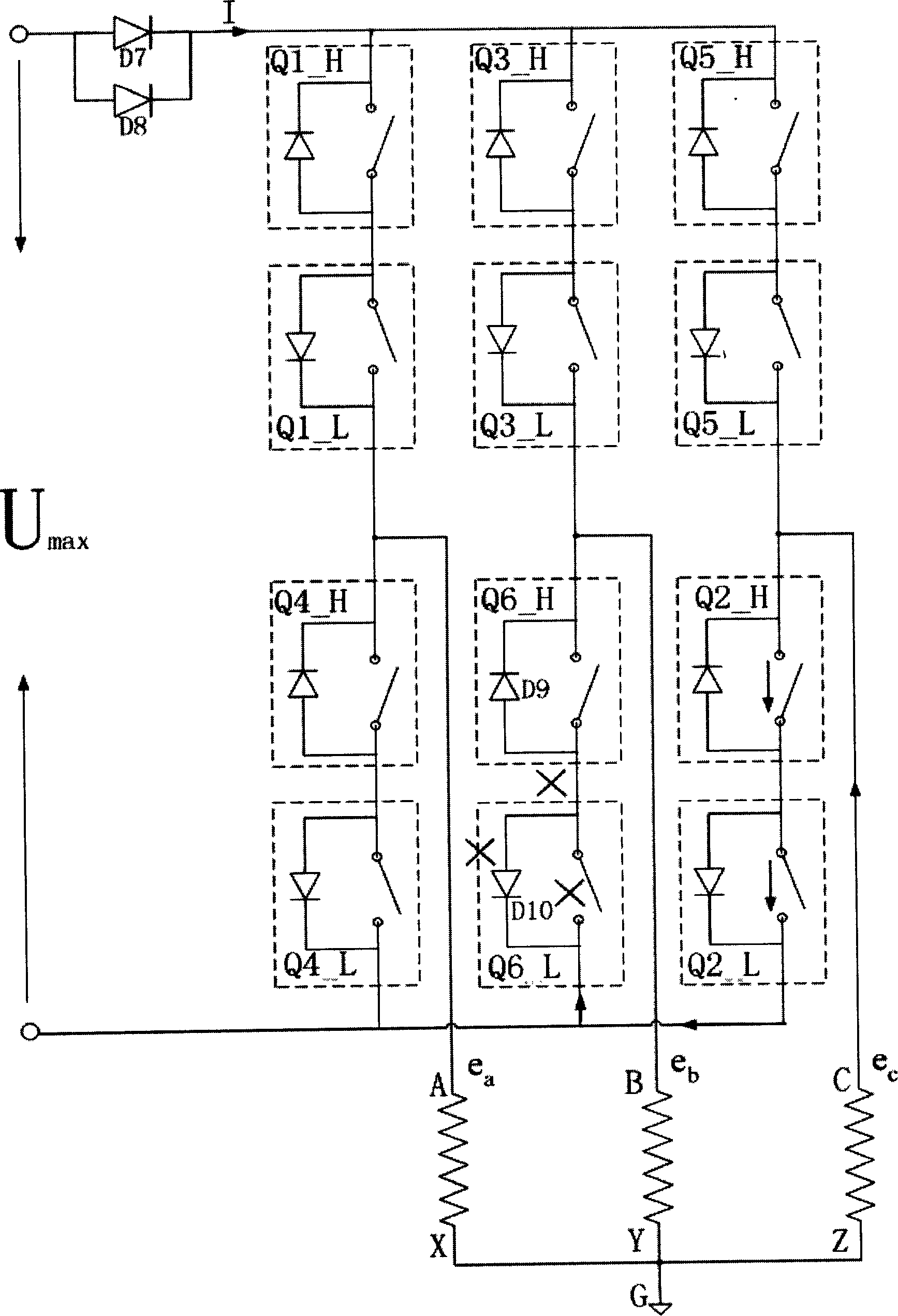
[0025] The embodiment of the present invention is a 28V field weakening drive device. like Figure 4 shown. MOSFET (Metal-Oxide-Semiconductor Field Effect Transistor) adopts IRFP460, and a pair of MOSFET (Metal-Oxide-Semiconductor Field Effect Transistor) S poles (sources) of each bridge arm are connected, and the connected ground is suspended. The G poles (gates) of Q1_H and Q1_L are connected and triggered simultaneously by T1; the G poles (gates) of Q3_H and Q3_L are connected and triggered by T3 simultaneously; the G poles (gates) of Q5_H and Q5_L are connected and triggered simultaneously by T5 , the G poles (gates) of Q4_H and Q4_L are connected, and are triggered simultaneously by T4; the G poles (gates) of Q6_H and Q6_L are connected, and are triggered by T6 at the same time; trigger. Connect a transient voltage suppressor D1, D3, D5, D4, D6, D2 in parallel to the MOSFET (Metal-Oxide-Semiconductor Field Effect Transistor) Q1_L, Q3_L, Q5_L, Q4_L, Q6_L, and Q2_L under...


PUM


Abstract

This invention relates to a weak magnet driving device for a permanent magnetic brushless DC motor, which connects a same MOSFET in series and reversely under the MOSFET of each upper bridge arm and lower bridge arm on the basis that a traditional magnet brushless DC motor three phase bridge drive device connects six MOSFET with a three-phase bridge reverse drive circuit to connect the S pole of the corresponding two to effectively eliminate circulation flow and increase the speed ratio of the brushless DC motor.

Description

(1) Technical field [0001] The invention relates to a motor driving device, in particular to a field-weakening driving device suitable for a permanent magnet brushless DC motor. (2) Background technology [0002] In many fields such as electric vehicles, CNC machine tools, household appliances, disk drives, and wind power generation, permanent magnet brushless DC motors are the best choice for comprehensive performance due to their simple structure, high power density, and large output. However, the excitation magnetomotive force of a permanent magnet motor is generated by a permanent magnet and cannot be adjusted. Therefore, its speed regulation range is not wide enough, and its speed regulation range is often expanded at the cost of increasing the power supply. For example, an electric vehicle travels at a speed of 0 to more than 100 kilometers per hour, and the speed of the driving motor must run from 0 to several thousand rpm or even tens of thousands of rpm. In the pro...

Claims


Application Information

Patent Timeline
IPC IPC(8): H02P6/10
Inventor 李榕刘卫国刘景林刘向阳
Owner NORTHWESTERN POLYTECHNICAL UNIV
Why Eureka
Try Eureka