Fixed carriageway for rail vehicles and method of manufacturing the same

A road and vehicle technology, applied in the field of fixed roads, can solve problems such as being no longer detectable

CN1854392AInactive Publication Date: 2006-11-01RAIL ONE GMBH
0 Cites 2 Cited by

Patent Information

Authority / Receiving Office
CN · China
Patent Type
Applications(China)
Current Assignee / Owner
Publication Date
2006-11-01
Estimated Expiration
Not applicable · inactive patent

Smart Images

  • Figure 1
    Figure 1
  • Figure 2
    Figure 2
  • Figure 3
    Figure 3
Patent Text Reader

Abstract

Fixed carriageway for rail vehicles having sleepers embedded in a carriageway panel and a reinforcement includes plural longitudinal and transverse rods disposed parallel and transverse to the sleepers, wherein the longitudinal rods and transverse rods are electrically isolated from one another.
Need to check novelty before this filing date? Find Prior Art

Description

technical field

[0001] The invention relates to a fixed roadway for rail vehicles having a sleeper embedded in the road slab and a reinforcement structure comprising a plurality of longitudinal and transverse reinforcement arranged in the road slab parallel and transverse to the sleeper . Background technique

[0002] The term "fixed road" denotes a track route with a superstructure in which gravel is replaced by other materials such as concrete or asphalt. When building a fixed road, the sleepers are adjusted and embedded in the pouring material, thus forming the road slab. The substructure of the road slab can comprise a hydrodynamically bonded support layer, a gravel support layer, a frost protection layer, a membrane or a geotextile.

[0003] When working on track routes, it is necessary to know whether a given rail section is free or whether vehicles are present there. For this purpose, track current circuits can be used, in which an audio signal is fed into the rail...

Examples

Embodiment Construction

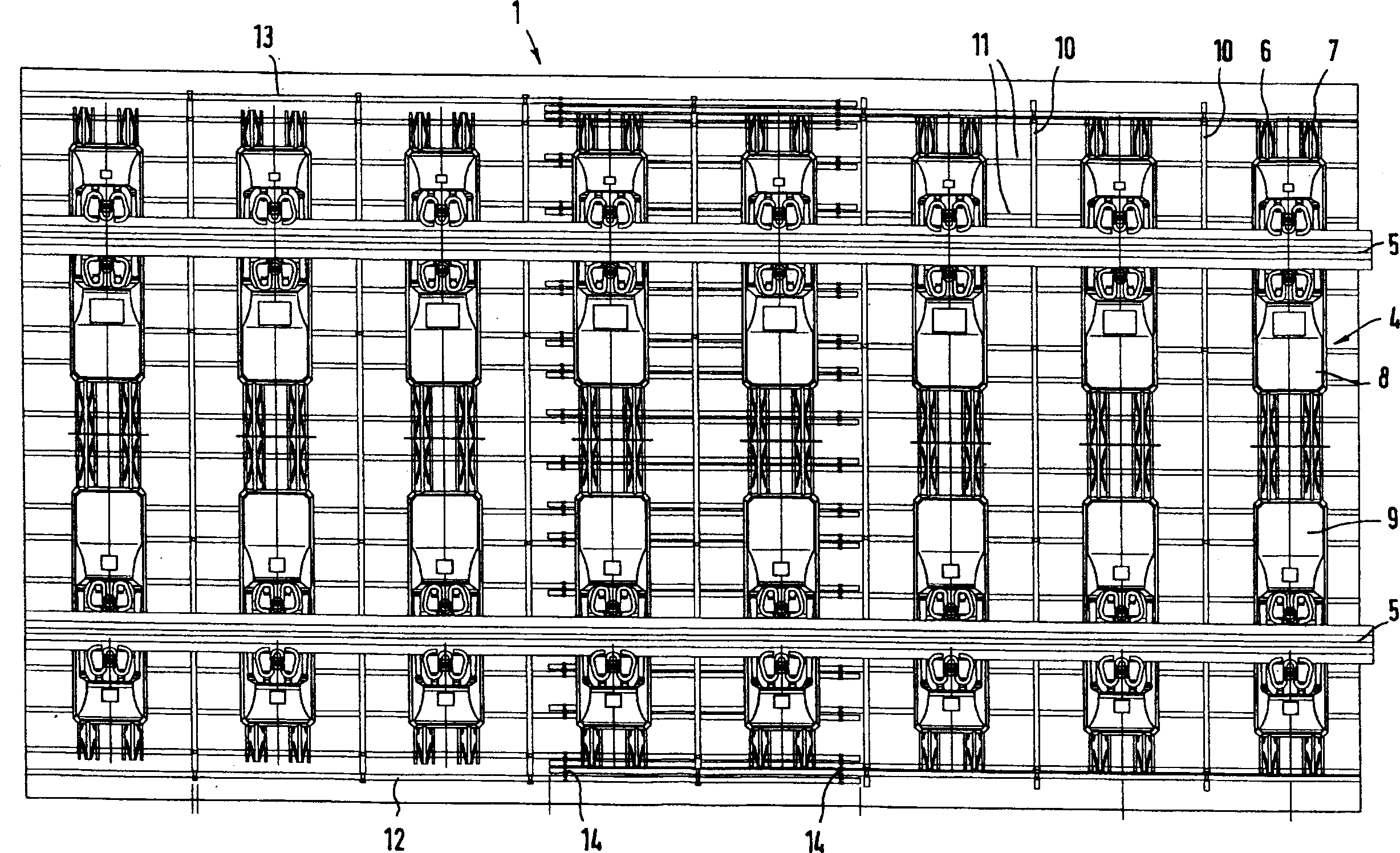
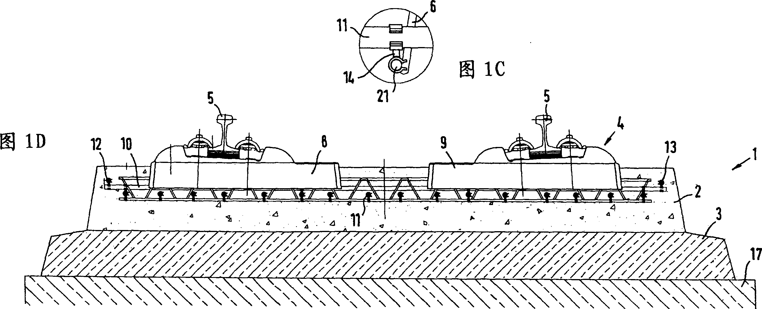
[0034] exist Figure 1A , 1B The fixed roadway 1 shown in and 1D consists essentially of a road slab 2 made of concrete, which in the exemplary embodiment shown is supported on a hydraulically bonded support layer as substructure 3 . The substructure 3 rests on the antifreeze layer 17 . A sleeper 4 is embedded in the road slab 2, and the sleeper 4 is designed as a double-block sleeper and carries a steel rail 5. Each sleeper 4 comprises two parallel grid supports 6 , 7 connected to sleeper blocks 8 , 9 made of concrete.

[0035] From Figure 1A As best shown in , a transverse reinforcement 10 is arranged between two adjacent sleepers in each case as reinforcement. In addition, the transversely extending struts of the grid supports 6, 7 are also used as transverse reinforcement for strengthening the structure.

[0036] In addition, the reinforcing structure comprises longitudinal reinforcements 11 arranged perpendicular to the transverse reinforcements, said longitudinal rei...