Al technical title is built by PatSnap Al team. It summarizes the technical point description of the patent document.
A sub-filter and optical path technology, applied in the field of optical switches, optical routers, and optical filters, can solve problems such as confusion, noise, and lost signals
Inactive Publication Date: 2006-11-01
ARRYX INC
View PDF3 Cites 4 Cited by
Summary
Abstract
Description
Claims
Application Information
AI Technical Summary
This helps you quickly interpret patents by identifying the three key elements:
Problems solved by technology
Method used
Benefits of technology
Problems solved by technology
This creates confusion within one band, resulting in an uneven transmission of light (signal) from
Method used
Image
Click on the blue label to locate the original text in one second.
Reading with bidirectional positioning of images and text.
Examples
Embodiment Construction
[0106] Certain terms will be used in the following description for convenience and reference, but not as a limitation. Brief definitions are provided below:
[0107] A. "Evanescent waves" are waves that are generated when a wave enters a region where it cannot travel. In particular, such waves are characterized by an exponential decay in amplitude with distance into regions into which they cannot transmit.
[0108] B. "WGM" refers to whispering gallery mode, which is a property of resonant structures and can be used for optical channels and resonant structures of a specific wavelength between one or more optical fibers via evanescent waves.
[0109] C. "Sub-beam" means a sub-beam of light or other energy generated by directing light or other energy sources (such as light generated by a laser or from the collimated output of a light-emitting diode) through a medium, wherein the medium diffracts light or other energy sources into two or more sub-beams. An example of a sub-bea...
PUM
Abstract
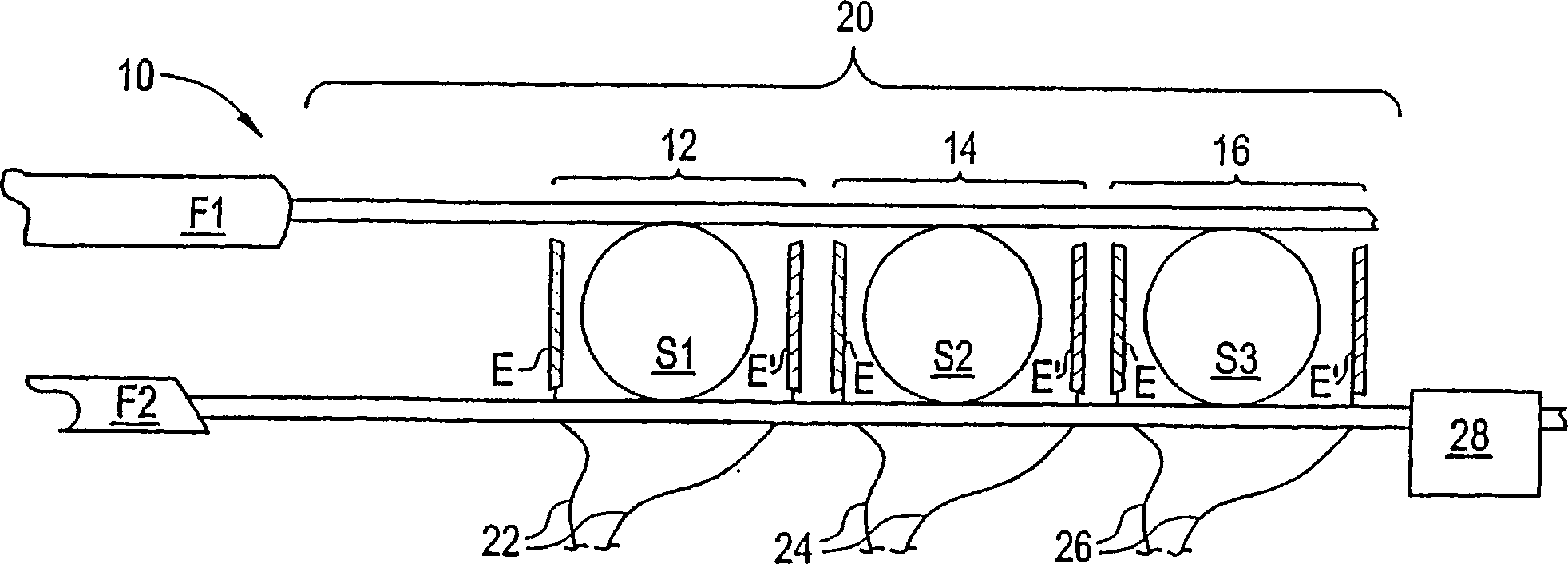
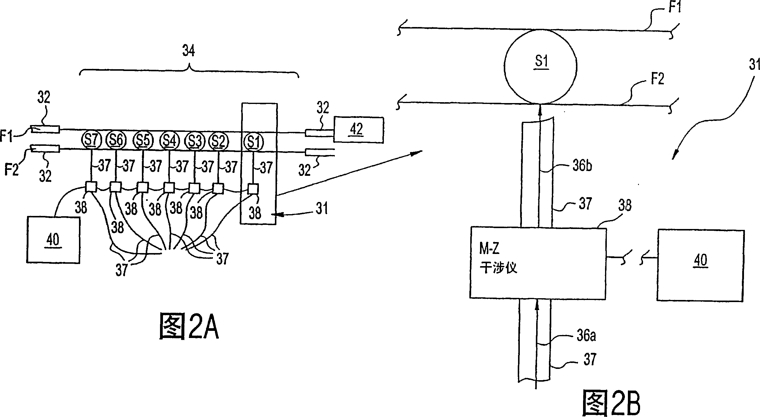
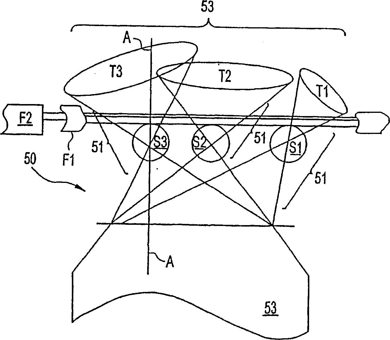
Our invention relates generally to an optical switch (31) and an optical router (10) to rapidly route signals from particular channels (22, 24) within an optical band by using optical switches (20) which utilize a controlled whispering gallery mode (WGM) resonance of dielectric microspheres (S1, S2, S3) to optically switch signals. Another invention relates to optical filters which use a WGM resonate structure (150) to isolate and switch specific optical signals between waveguides (F1, F2). In other inventions, the filter (100) is switched 'on/off' by signal loss within a WGM resonate structure (150) which disrupts the WGM resonance; the filter (100) isolates and switches a specific wavelength signal from among a group of signals of different wavelengths; and is switched 'off' by adjusting the index of refraction of the resonate structure to become substantially similar to the index of refraction of the surrounding medium.
Description
[0001] This application is a divisional application of the Chinese invention patent application with the application number 02816302.8, the application date is June 20, 2002, and the invention name is "optical switch, optical router and optical filter". [0002] This application is a PCT application and asserts U.S. Application No. 09 / 886,698 filed on June 20, 2001, U.S. Application No. 10 / 118,532 filed on April 8, 2002, and U.S. Application No. 10 / 118,532 filed on April 8, 2002. Priority to Application No. 10 / 118,531, U.S. Application No. 10 / 118,709, filed April 8, 2002, and U.S. Application No. 10 / 118,760, filed April 8, 2002, the entire contents of each of which are incorporated by reference way is incorporated into this article. [0003] related technology [0004] Various publications are incorporated throughout this application. In order to more fully describe the state-of-the-art to which this invention pertains, the entire disclosures of these publications are incorpor...
Claims
Application Information
Patent Timeline
Application Date:The date an application was filed.
Publication Date:The date a patent or application was officially published.
First Publication Date:The earliest publication date of a patent with the same application number.
Issue Date:Publication date of the patent grant document.
PCT Entry Date:The Entry date of PCT National Phase.
Estimated Expiry Date:The statutory expiry date of a patent right according to the Patent Law, and it is the longest term of protection that the patent right can achieve without the termination of the patent right due to other reasons(Term extension factor has been taken into account ).
Invalid Date:Actual expiry date is based on effective date or publication date of legal transaction data of invalid patent.
