Optical focal plane data coupler

a data coupler and optical focal plane technology, applied in the field of data coupling, can solve the problems of large size requirements, relatively high power levels of modulation techniques, and limited application of electrooptic modulation techniques, and achieve the effect of little electrical power

Active Publication Date: 2009-03-05
LOCKHEED MARTIN CORP
View PDF6 Cites 18 Cited by
  • Summary
  • Abstract
  • Description
  • Claims
  • Application Information

AI Technical Summary

Benefits of technology

[0010]According to one embodiment of the present invention, electrical signals from detectors (pixels) of an imaging focal plane array (or antenna elements of an antenna array) are coupled to optical waveguides by way of micro-resonators in the form of whispering gallery mode resonators. The resonators modulate optical signals in the waveguides based on the electrical signals from the detectors or antenna elements. In such manner, the signals received by the array are converted into the optical domain, allowing subsequent optical processing and / or distribution.
[0011]Each detector / antenna element involved (which can correspond to an individual picture element or “pixel”) can be identified by the specific wavelength and waveguide through which its signal is coupled, enabling subsequent optical processing of the signals. Electro-optic modulation systems or couplers according to the present invention may consequently be very compact, allowing it to fit within the small form factor of the arrays, and to require very little electrical power.

Problems solved by technology

Such prior electro-optic modulation techniques have been useful for some application but have been limited for other applications by exhibiting low bandwidth, low gain, and high noise figures.
Additionally, such prior art modulation techniques have required relatively high power levels for sufficient modulation—on the order of 1 Watt of microwave power and have required large size requirements (or form factors) due to the significant optical paths required for sufficient modulation to take place.

Method used


Image

  • Optical focal plane data coupler
  • Optical focal plane data coupler
  • Optical focal plane data coupler

Examples


Embodiment Construction

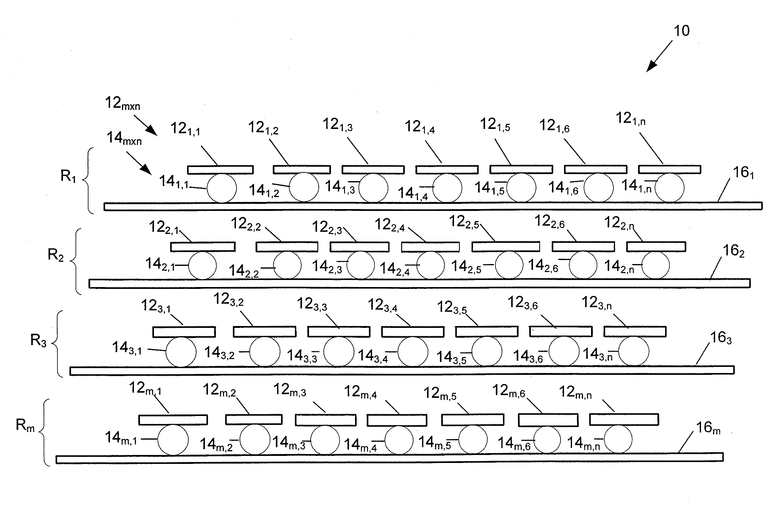
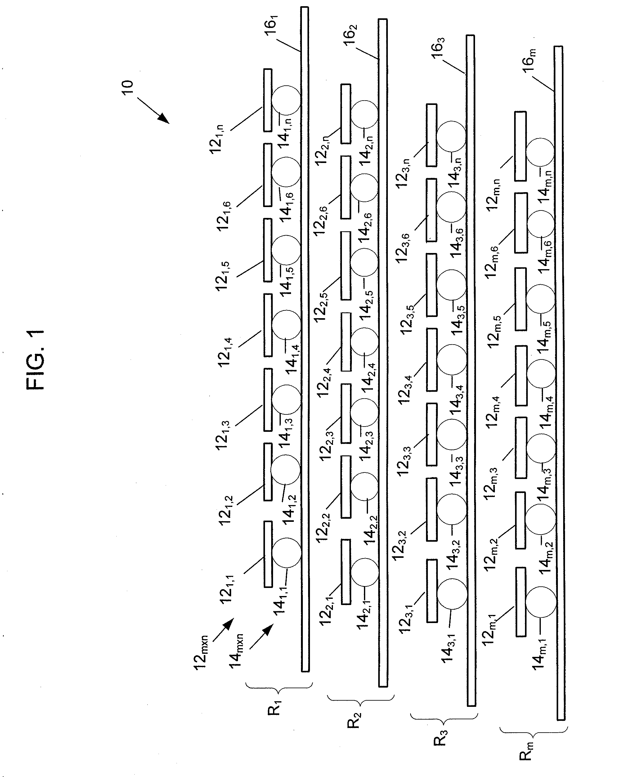
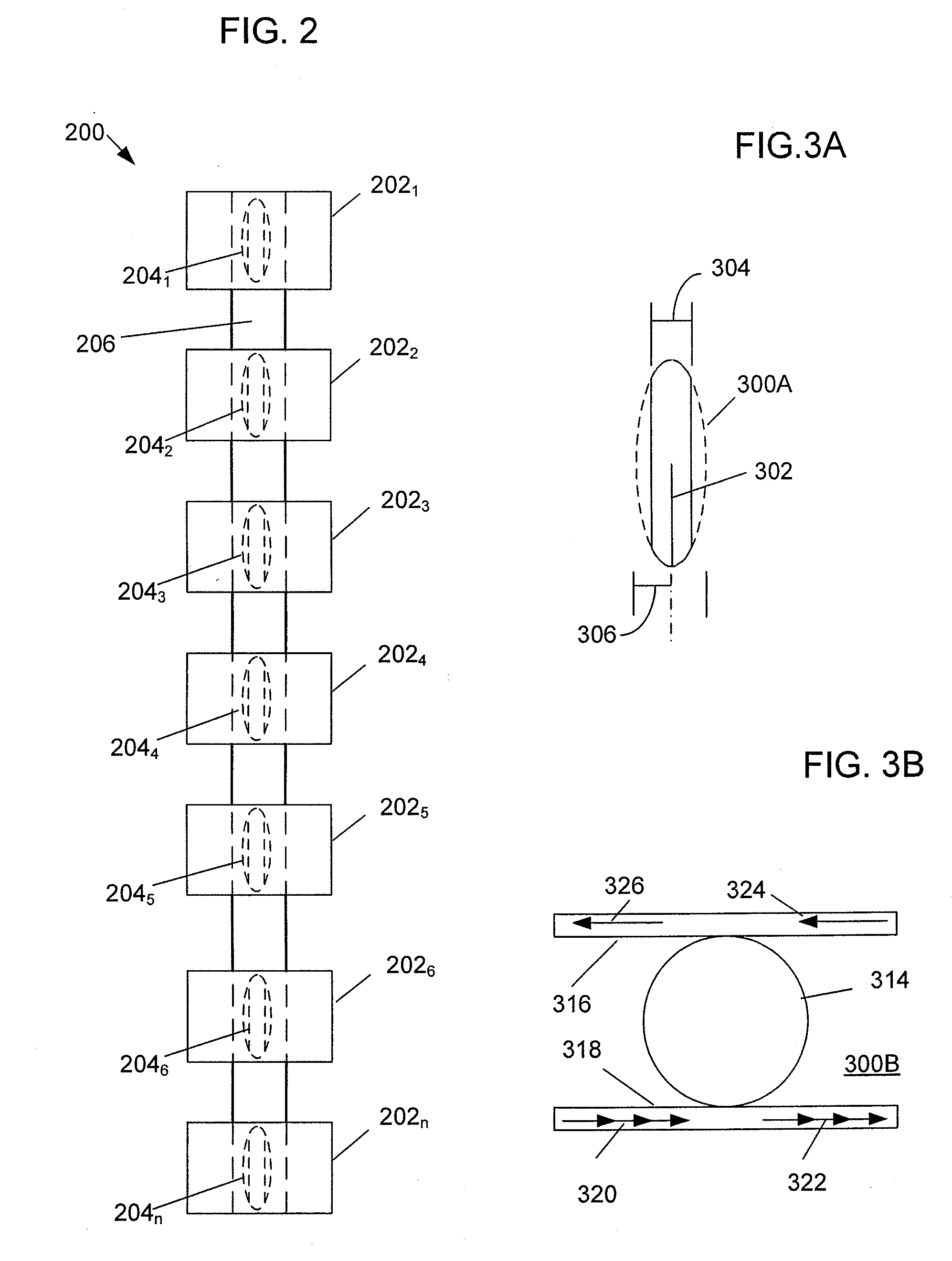
[0026]The present invention is directed to methods and systems, including photonic architectures, that utilize micro-resonators in the form of whispering gallery mode resonators for modulation of optical carrier signals based on signals detected from an antenna array coupled to the whispering gallery mode resonators. When the micro-resonator is made of electro-optic material, the resonant wavelength can be made to be sensitively dependent upon applied voltages, thus modulating any continuous wave (CW) optically coupled signal. Optical whispering mode gallery resonator modes propagate around the equator of the disk or toroid (or sphere) structure with relatively high quality factors (Q) owing to the total internal reflection and possible low absorption losses of the resonator material.

[0027]Because of the relatively long interaction lengths between the electrical and optical fields in a whispering gallery mode resonator made of suitable electro-optical material, such resonators can b...


PUM

PropertyMeasurementUnit
wavelengthaaaaaaaaaa
diameteraaaaaaaaaa
optical signalsaaaaaaaaaa

Abstract

Systems are disclosed that utilize electrical signals from detectors of an imaging focal plane array or antenna elements of an antenna array to modulate optical signals. Antenna or focal plane array elements are coupled to optical waveguides by way of whispering gallery mode resonators made of electro-optic material. The resonators modulate optical signals in the waveguides based on the electrical signals from the detectors / antenna elements. The signals received by the array are converted into the optical domain, allowing subsequent optical processing and / or distribution. Each detector / antenna element involved can be identified by the specific wavelength and waveguide through which its signal is coupled, enabling subsequent optical processing of the signals such as by wavelength division multiplexing systems. Additionally disclosed are imaging sensor photonic systems that include WDM components and other optical components such one or more optical narrow-band amplifiers and / or filters. Related electro-optic modulation and tuning methods are also described.

Description

RELATED APPLICATION[0001]This application claims the benefit of U.S. Provisional Patent Application No. 60 / 969,922 filed 4 Sep. 2007, the contents of which are incorporated by reference herein in their entirety.STATEMENT REGARDING FEDERALLY SPONSORED RESEARCH OR DEVELOPMENT[0002]Not Applicable.FIELD OF THE INVENTION[0003]The present invention generally relates to data coupling and, in particular, relates to methods and systems for electro-optically modulating signals from an antenna array, such as a photodiode focal plane array.BACKGROUND[0004]Antenna arrays, including focal plane image sensors such as charge coupled device (CCD) diode arrays, are used in a number of signal transmission and receiving applications as well as imaging applications and over a large range of frequencies of the electromagnetic spectrum. Traditionally, signals received at an antenna array were electronically amplified and converted to an intermediate frequency for subsequent electronic signal processing.[0...

Claims


Application Information

Patent Timeline
Patent Type & Authority Applications(United States)
IPC IPC(8): G02F1/225G02F1/295
CPCG02B6/29341G02B6/29343G02F2203/15G02F2203/055G02F1/0118
Inventor KARRAS, THOMAS W.
Owner LOCKHEED MARTIN CORP
Why Eureka
Try Eureka