Coiled Evanescent Optical Sensor

a technology of optical sensors and evanescent light, applied in the field of evanescent light, can solve the problems of increasing the overall physical size of the sensor, the loss of devices, and the spatial delocalization of the measuremen

Active Publication Date: 2011-02-24
OFS FITEL LLC
View PDF16 Cites 18 Cited by
  • Summary
  • Abstract
  • Description
  • Claims
  • Application Information

AI Technical Summary

Benefits of technology

[0011]It is an advantage of the compact nature of the coiled structure of the present invention that spatial delocalization of the measurement, associated with relatively “long” prior art sensors, is essentially eliminated.

Problems solved by technology

On the other hand, increasing the length L results in increasing the overall physical size of the sensor.
The latter is undesirable for at least two reasons.
First, this causes spatial delocalization of the measurement since the ambient may change over the length of the interferometer arm.
Second, many applications require the use of a “miniature” sensor (for example, in a “lab on a chip” application).
However, these devices are known to experience relatively high losses and cannot provide the degree of sensitivity required for many applications.
Input / output coupling to / from these photonic wire devices is also problematic and introduces unwanted optical losses into the system.

Method used


Image

  • Coiled Evanescent Optical Sensor
  • Coiled Evanescent Optical Sensor
  • Coiled Evanescent Optical Sensor

Examples


Embodiment Construction

[0020]An evanescent optical sensor useful for analyzing various parameters of the ambient environment (e.g., temperature, pressure, acoustic, refractive index, etc.) is formed from a coiled configuration of an optical fiber or microfiber. For the purposes of the present invention, the term “microfiber” is defined as a fiber with a diameter on the order of one micron (or less than / or on the order of the wavelength of an optical signal propagating through the fiber). It is contemplated that the coiled sensor of the present invention may be constructed of either conventional optical fiber (having a diameter on the order of ten to a hundred microns) or microfiber, where differences in sensitivity of various embodiments can be attributed, in part, to the selection of either fiber or microfiber.

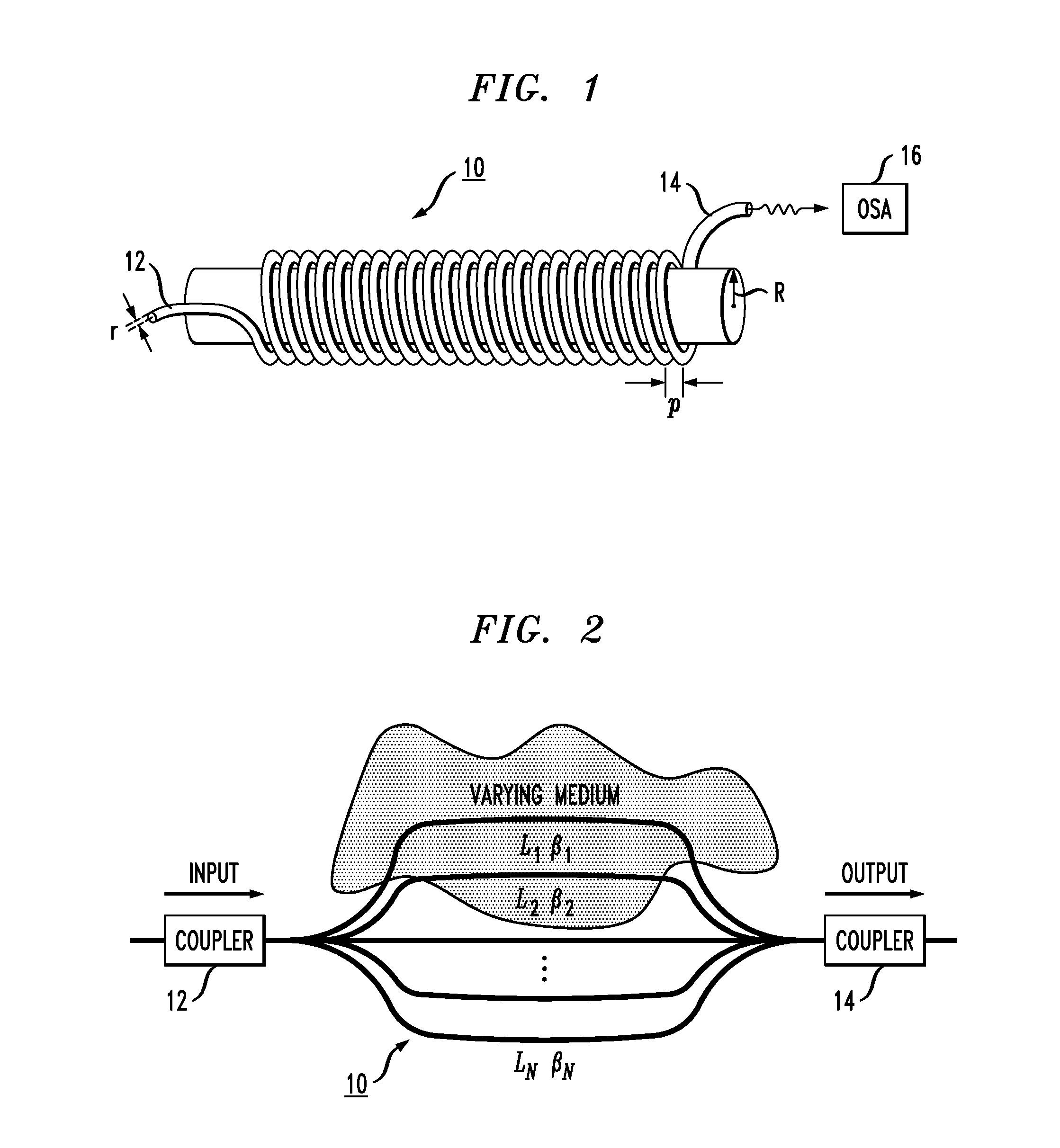
[0021]FIG. 1 illustrates an exemplary coil 10 that may be used to form the evanescent optical sensor of the present invention. Coil 10 may be formed of either optical fiber or microfiber and is def...


PUM


Abstract

An evanescent optical sensor is formed as a coil of either optical fiber or microfiber. By coiling the fiber/microfiber, the overall size of the sensor is significantly reduced when compared to “straight path” prior art fiber sensors, yet exhibits a similar degree of sensitivity, in operation, an optical signal is coupled into a fiber coil that has been immersed in an ambient to be analyzed. The use of a coil configuration results in creating a plurality of whispering gallery modes (WGMs) that will propagate along the coil by reflecting from the surface of the curved fiber/microfiber forming the coil. The interference between these modes will be modified as a function of the properties of the ambient environment within which the coil is immersed. Environmental changes cause variations in the optical length of the coil as “seen” by the various modes, and the interference of the modes is analyzed by studying the transmission spectrum at the output of the coil.

Description

CROSS-REFERENCE TO RELATED APPLICATIONS[0001]This application claims the benefit of US Provisional Application No. 61 / 234,834, filed Aug. 18, 2009 and herein incorporated by reference.TECHNICAL FIELD[0002]The present invention relates to an evanescent optical sensor and, more particularly, to an evanescent optical sensor in the form of a fiber coil.BACKGROUND OF THE INVENTION[0003]Optical waveguides and, in particular, optical fibers, are often used for sensing changes in an ambient medium. Optical sensors have been used to measure changes in various parameters such as temperature, pressure, sound, refractive index and the like. In many cases, these changes are detected by monitoring the transmission (or reflection) spectrum of light as it propagates along an optical waveguide disposed within the ambient. Some optical sensors function as evanescent sensors based on the detection of changes in light propagating through an optical waveguide due to the optical mode that evanescently pe...

Claims


Application Information

Patent Timeline
Patent Type & Authority Applications(United States)
IPC IPC(8): G01B9/02
CPCG01D5/35329G01N21/552G01K11/32
Inventor SUMETSKY, MIKHAIL
Owner OFS FITEL LLC
Why Eureka
Try Eureka