

Gateway system
A gateway and main gateway technology, applied in the field of gateway systems, can solve problems such as impossible communication, and achieve the effect of high gateway redundancy
- Summary
- Abstract
- Description
- Claims
- Application Information
AI Technical Summary
Problems solved by technology
Method used
Image

Examples
no. 1 example
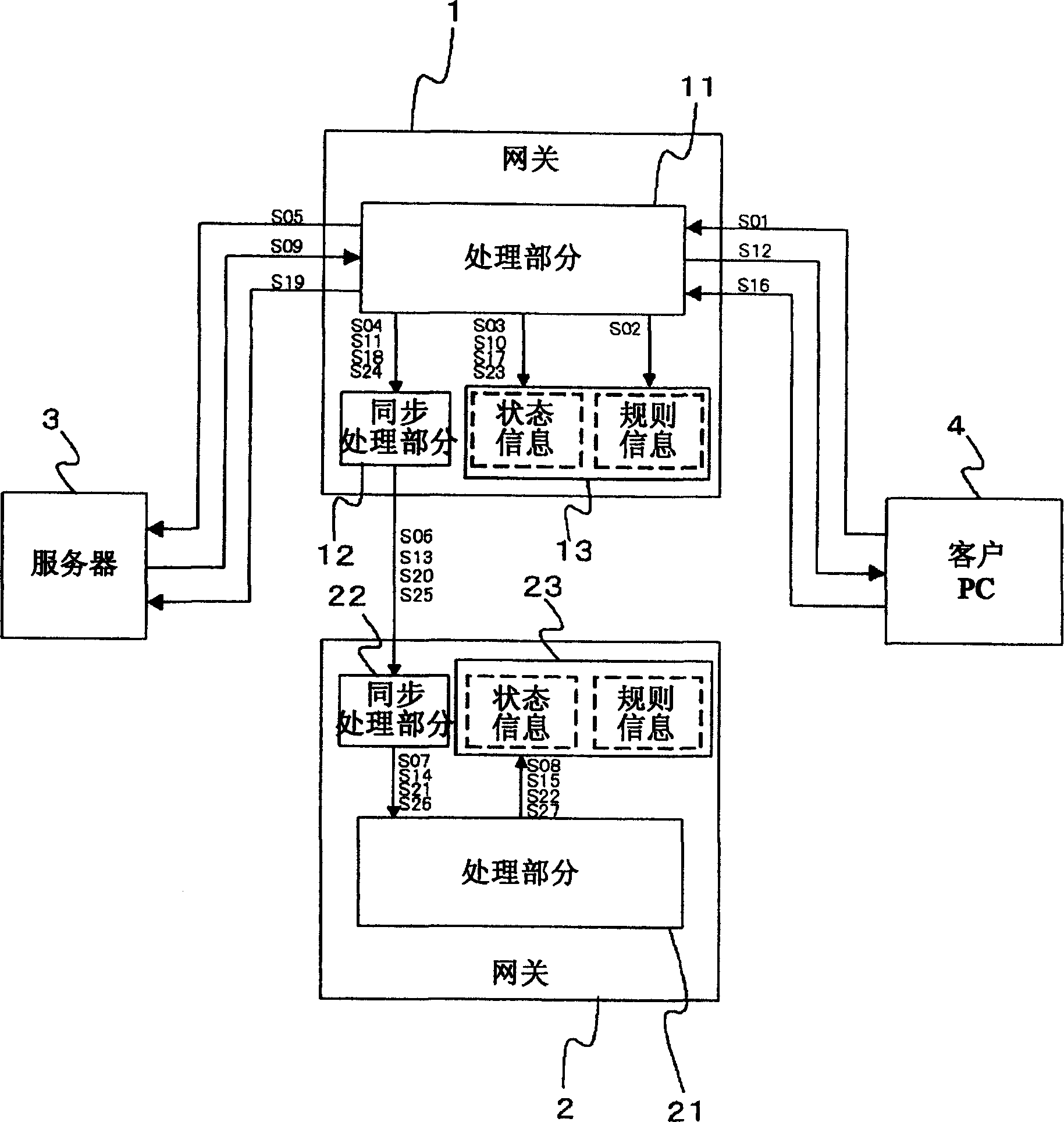
[0073] figure 1 is a block diagram showing the first embodiment of the gateway system according to the present invention.
[0074] exist figure 1 Among them, gateways 1, 2 have processing sections 11, 21, synchronization processing sections 12, 22, and storage sections 13, 23. The processing section 11, 21 is a section for processing packets and performs different processing according to the gateway type (gateway 1 or 2); for example, if the gateway is a NAT unit, the processing section performs address translation processing; if the gateway is a firewall unit, The processing part then performs screening; if the gateway is a translator, the processing part performs protocol translation processing, and so on.
[0075] The storage section 13, 23 is a memory in which rule information and state information are stored by the processing section 11, 21. For example, if the gateway is a NAT unit or a translator, the rule information corresponds to address translation rules; if th...
no. 2 example
[0139] Figure 6 is a block diagram showing a second embodiment according to the present invention.
[0140] In a second embodiment, a gateway is added. The structure of each gateway is the same as that explained above, so it will not be discussed again. exist Figure 6 , gateway 2 is not shown for convenience
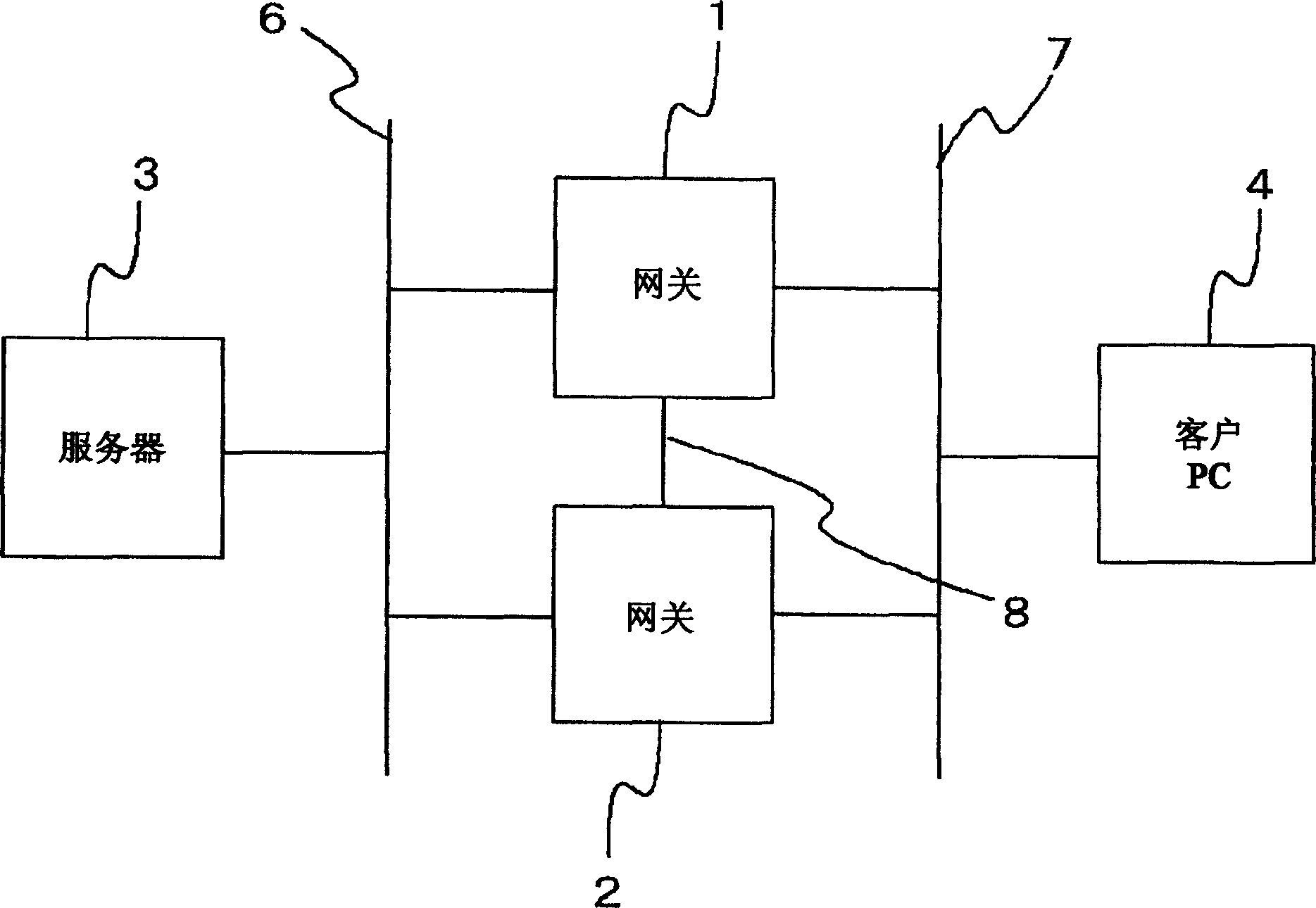
[0141] Figure 7 is a schematic diagram illustrating a network configuration according to the present invention.
[0142] exist Figure 7 In , server 3 is connected to gateways 1, 2 and 10 through network 6. Client PC4 is connected to gateways 1, 2 and 10 via network 7. In the communication between the server 3 and the client PC4, the gateways 1 and 2 work as a group. At this time, gateway 1 works as a master gateway, and gateway 2 works as a slave gateway. The gateway 10 does not work (power is not turned on, function is invalid, etc.).
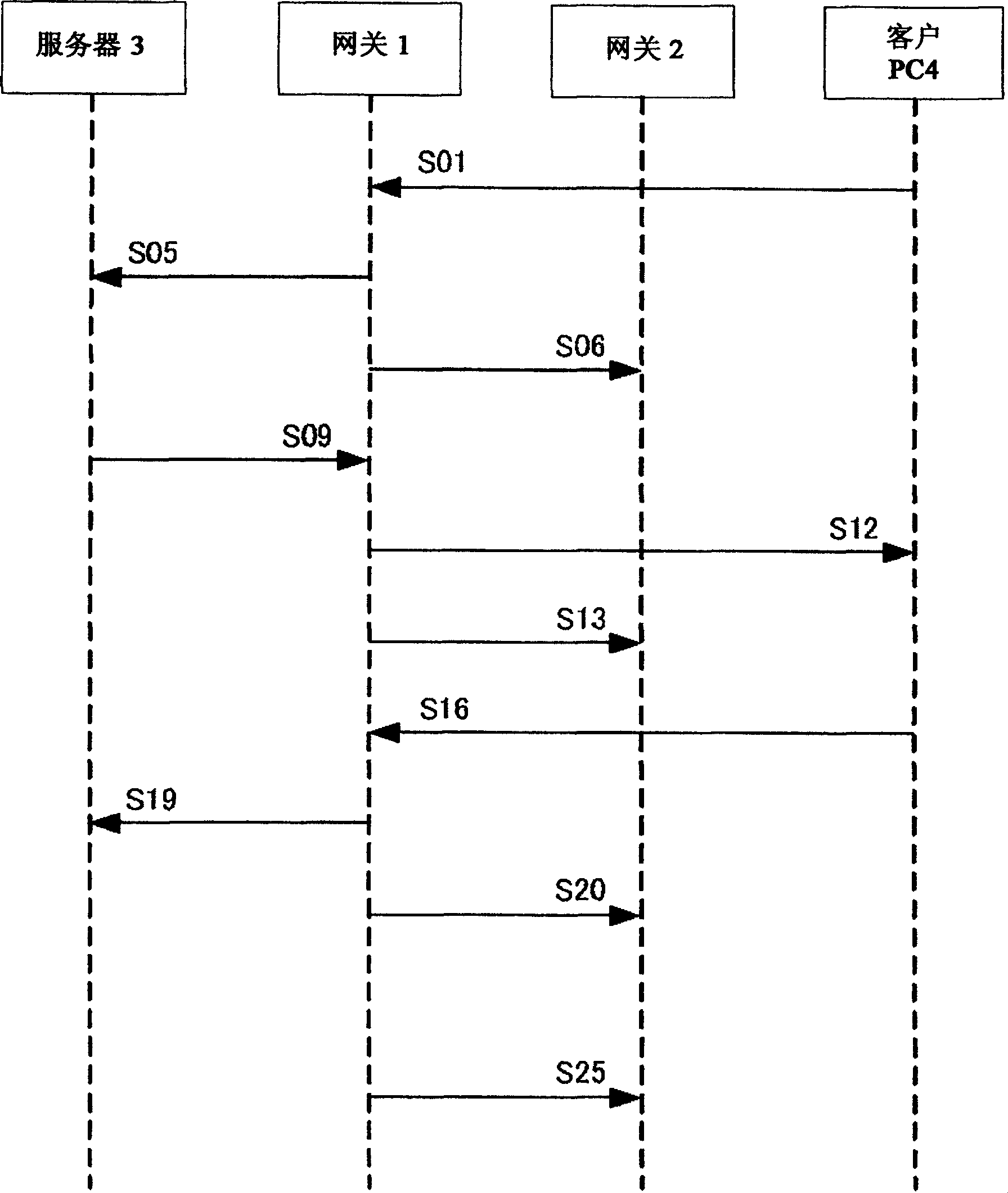
[0143] Figure 8 yes Figure 6 Flowchart of the packets in the configuration. combine Figure 6 and Figure 8 The op...
no. 3 example
[0156] Figure 9 is a block diagram showing a third embodiment according to the present invention.
[0157] exist Figure 9 Among them, the gateways 110, 140 are composed of processing sections 111, 141, synchronization processing sections 112, 142, and storage sections 113, 143, like the above-mentioned gateways, and therefore their configuration will not be discussed again. For simplicity, the gateways 120 and 150 described later are not shown in the figure.
[0158] The gateway 130 has a processing section 131 , storage sections 133 a and 133 b , and a synchronization processing section 132 . The processing section 131 and the synchronization processing section 132 are functional blocks similar to the corresponding functional blocks of any other gateway.
[0159] Rule information (not shown) and status information A are stored in the storage section 133 a by the processing section 131 , and status information B is stored in the storage section 133 b by the processing sec...
PUM
 Abstract
Description
Claims
Application Information