
Equipment and method of high-efficiency high-speed environmentally-friendly energy-saving sludge treatment system

A sludge treatment, environmental protection and energy-saving technology, applied in the direction of temperature control sludge treatment, dehydration/drying/thickened sludge treatment, etc., can solve the problems of human health hazards, waste of resources, secondary pollution of the environment, etc.

Active Publication Date: 2012-05-30
溧阳正昌干燥设备有限公司 +1
View PDF8 Cites 19 Cited by
  • Summary
  • Abstract
  • Description
  • Claims
  • Application Information

AI Technical Summary

Problems solved by technology

[0002]At present, the domestic sludge treatment process generally adopts sludge concentration, sludge digestion, sludge dehydration, drying field, sanitary landfill, or agricultural use after digestion, and some It is directly concentrated and used for agriculture, but the sludge contains a large number of pathogenic microorganisms and residual heavy metal ions, and its biochemical properties are very unstable. Most of the sludge is directly buried in a sanitary landfill, which not only causes a waste of resources, but also causes secondary pollution to the environment. secondary pollution, thereby causing harm to human health

Method used


Image

  • Equipment and method of high-efficiency high-speed environmentally-friendly energy-saving sludge treatment system
  • Equipment and method of high-efficiency high-speed environmentally-friendly energy-saving sludge treatment system

Examples


Embodiment Construction

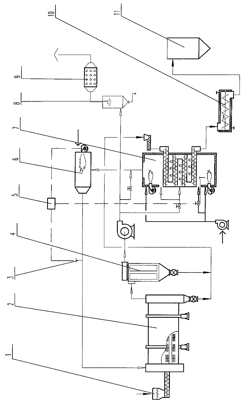
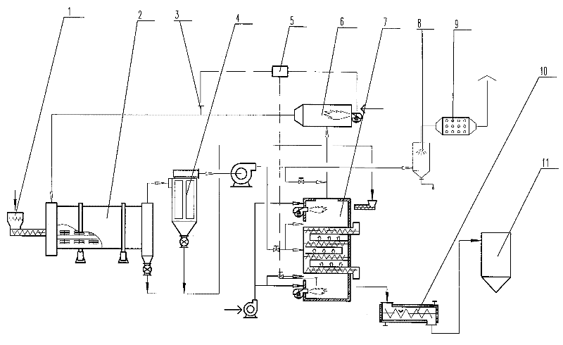
[0013] Such as figure 1 As shown, the sludge treatment system is mainly composed of a feeding device 1, a sludge dryer 2, a temperature sensor 3, a dust collector 4, a temperature controller 5, a spare furnace 6, a sludge carbonization furnace 7, and a wet dust collector 8. Photochemical deodorizer 9, cooling humidifier 10, storage bin 11, II temperature sensor 12, blower 13 and induced draft fan 14, etc., which communicate with each other through air ducts. Firstly, the standby furnace 6 is ignited and the temperature controller 5 controls the temperature of the hot air sent into the sludge dryer 2 by the air pipe through the I temperature sensor 3. When the temperature of the hot air sent into the sludge dryer 2 reaches the set drying temperature of 800°C, the wet sludge is fed The device 1 is put into the sludge dryer 2, and after the wet sludge is dried, it is sent to the activated sludge carbonization furnace 7, and then, the carbonized sludge particles enter the cooling ...


PUM


Abstract

The invention discloses a technique of sludge drying and carbonization, particularly a technique of a high-efficiency high-speed environmentally-friendly energy-saving sludge treatment system. The equipment mainly comprises a feeding unit, a sludge drier, a standby furnace, a sludge carbonization furnace, a temperature controller, a temperature sensor I, a temperature sensor II, a duster, a hydroscrubber, an photochemical deodorizer, a cooling humidifier, a storage bin, an induced draught fan, an air blower, a valve, and the like. The method is characterized in that the sludge is dried in the drier, then the dried sludge is put in the carbonization furnace for carbonization, wherein the temperatures of drying and carbonization are automatically controlled by the temperature controllers; the waste heat moisture discharged from the sludge drier is discharged safely after being subject to dedusting, recycling, photochemical deodorizing; the carbonized sludge particles are put into the storage bin after being subject to cooling and humidification. According to the invention, various germs can be killed; by using the combustion of the sludge to dry and carbonize the sludge, the carbonized product can be used as a soil amendment, an organic fertilizer, a snow-melting agent and the like, the advantages of energy saving, environmental protection, and continuous high speed operation are achieved, thus the invention deserves to be broadened.

Description

Technical field [0001] The invention relates to equipment and method of a fast, efficient, environment-friendly and energy-saving sludge treatment system, more precisely, relates to equipment and process of a continuous high-speed, energy-saving and environment-friendly sludge treatment system. Background technique [0002] At present, the domestic sludge treatment process generally adopts sludge concentration, sludge digestion, sludge dehydration, drying field, sanitary landfill, or agricultural use after digestion, and some are directly concentrated for agricultural use, but the sludge contains a large number of pathogenic microorganisms and residues. There are heavy metal ions, and their biochemical properties are very unstable. After most of the sludge is directly landfilled, it not only causes a waste of resources, but also causes secondary pollution to the environment, thus causing harm to human health. Contents of the invention [0003] In order to overcome the shor...

Claims


Application Information

Patent Timeline
IPC IPC(8): C02F11/12C02F11/18
Inventor 徐建华黄俊强朱宁张时英彭睿郑伟新
Owner 溧阳正昌干燥设备有限公司
Learn More