
Hydraulic gas storage cylinder

A gas storage tank, water pressure technology, applied in the field of biomass energy applications, can solve the problems of pool strength lamps, unfavorable stable combustion of stoves, inability to solve short-term peak gas consumption, loss of fermentation liquid between discharges, etc., to achieve gas Stable pressure, simple structure, stable gas storage effect

Inactive Publication Date: 2006-11-08
冯义华
View PDF0 Cites 2 Cited by
  • Summary
  • Abstract
  • Description
  • Claims
  • Application Information

AI Technical Summary

Problems solved by technology

[0003] 1. The air pressure changes repeatedly, which is unfavorable to the strength of the pool body and the stable combustion of lamps and stoves;
[0004] 2. It is prone to failures such as air leakage from the movable cover and loss of fermentation liquid in the discharge room;
[0007] 2. When discharging, the liquid level in the fermentation room drops, and the space in the fermentation room increases to form a negative pressure. The biogas in the gas storage hood flows back into the fermentation room, and the gas appliance cannot be used when discharging.
The gasification system is a first-stage pressure regulation transmission and distribution system. The pressure from the entire pipeline network to each user is provided by the pressure of the gas tank. Therefore, it is bound to cause the pressure to gradually decrease with the increase of the pipeline network. The user closest to the gas storage tank has the highest pressure, and the user farther away from the gas storage tank has the lower pressure. Generally speaking, the gasifier with continuous gas production cannot solve the short-term peak gas consumption

Method used


Image

  • Hydraulic gas storage cylinder
  • Hydraulic gas storage cylinder
  • Hydraulic gas storage cylinder

Examples


Embodiment Construction

[0017] Below in conjunction with accompanying drawing and specific embodiment the present invention is described in further detail:

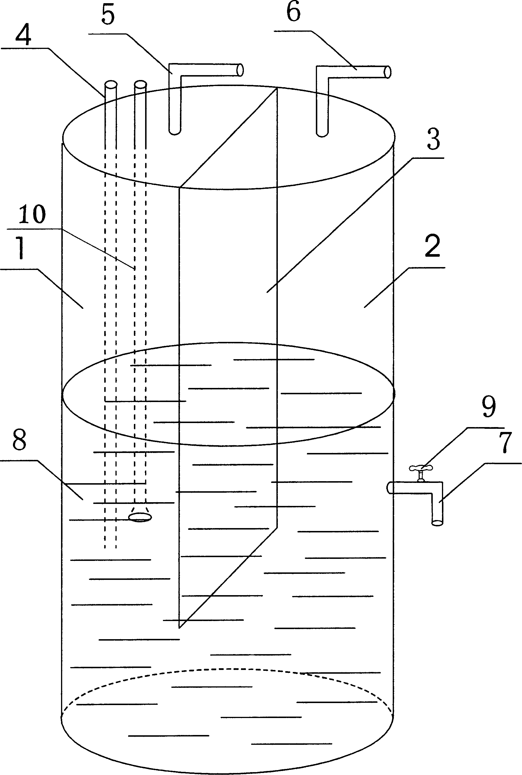
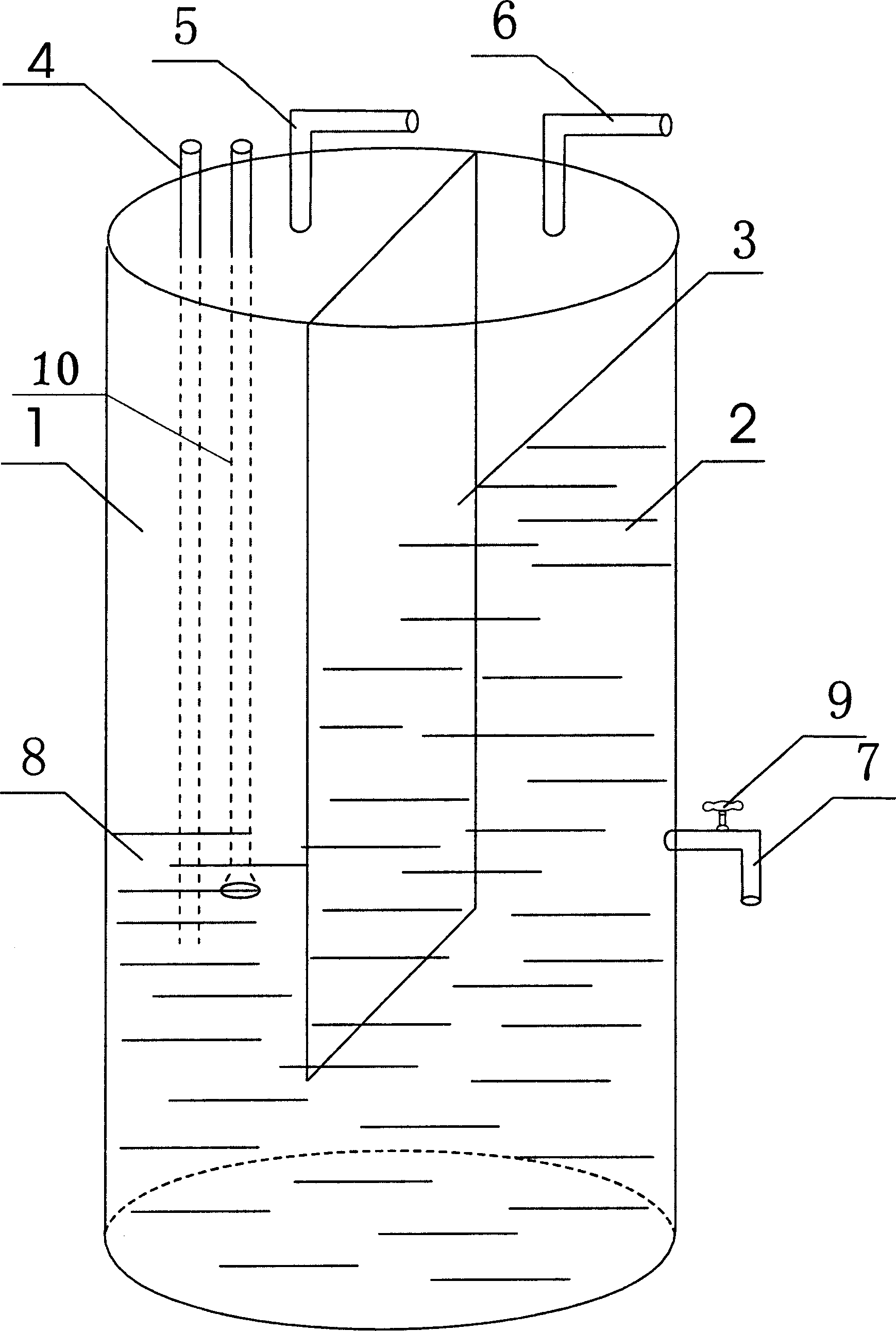
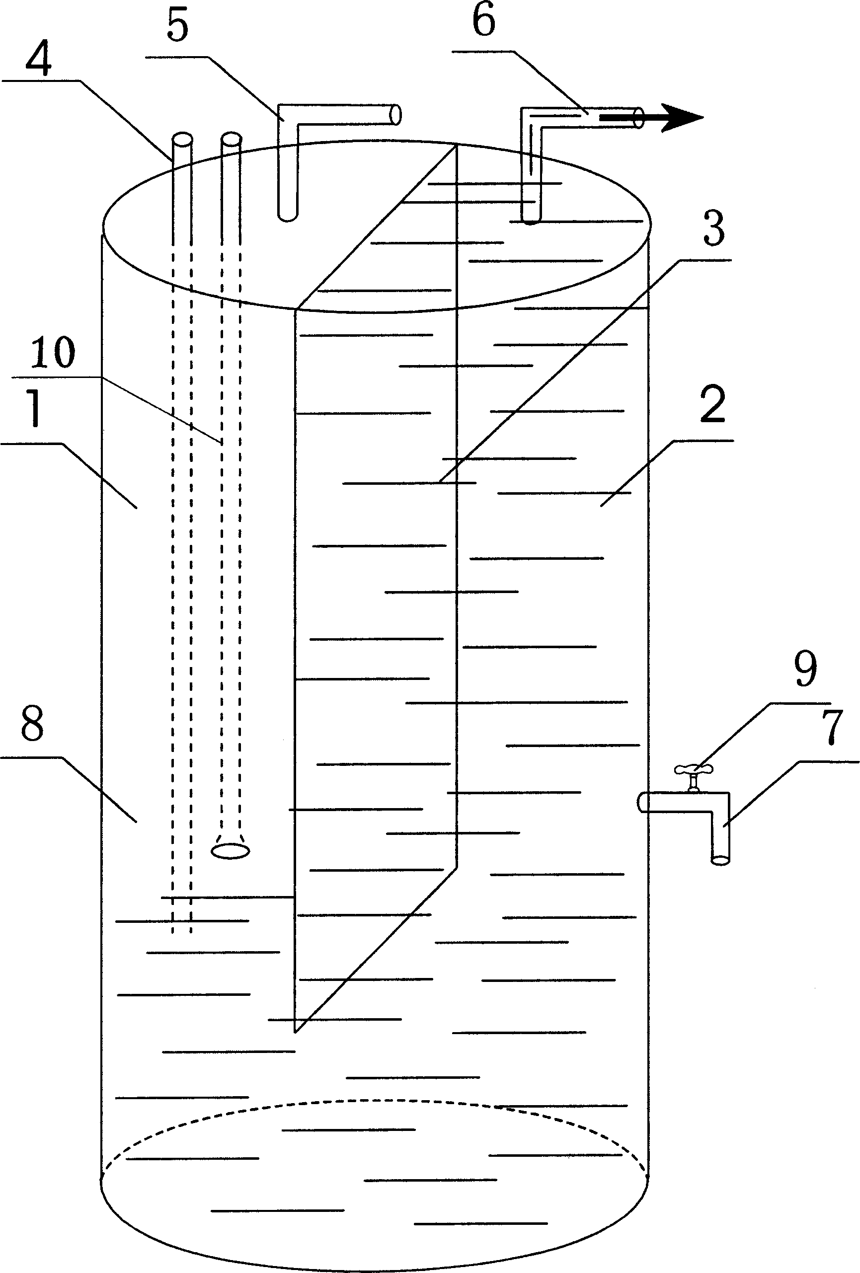
[0018] Such as figure 1 Among them, a partition 3 is provided between the air storage chamber 1 and the water pressure chamber 2, the lower end of the partition 3 is higher than the bottom surface of the tank body, and the top of the water pressure chamber 2 is provided with a water inlet and overflow pipe 6, from which the water inlet overflow pipe Water or solution 8 is injected into 6, and water or solution 8 flows into the air storage chamber 1 from the hydraulic chamber 2 through the lower end of the partition plate 3. Under normal pressure, the water levels in the air storage chamber 1 and the hydraulic chamber 2 are on the same level. When the gas outlet pipe 5 is closed and the shunt pipe 10 extends under the liquid surface, after the fermentation raw materials are decomposed or the stalk is gasified to produce gas, the gas will graduall...


PUM


Abstract

The hydraulic gas storage cylinder is one stable gas storing and supplying apparatus with stable gas pressure and high fuel gas purity. It consists of gas storing cavity, water pressure cavity, and water or solution. There are partition board set between the gas storing cavity and water pressure cavity, gas inlet pipe, gas outlet pipe and by-pass pipe in the top of the gas storing cavity, water inlet pipe and overflow pipe in the top of the water pressure cavity, and water draining pipe in the lower part of the water pressure cavity.

Description

technical field [0001] The invention relates to the technical field of biomass energy application, more specifically, it relates to a gas storage device for biogas or straw gasification gas. Background technique [0002] With the shortage of fossil energy, the development and utilization of biomass energy has been paid more and more attention, especially the application of biogas and straw gasification technology has been widely promoted. At present, there are two main ways to store biogas used in rural areas and industries. One is that the cavity is stored in the upper gas storage room of the hydraulic biogas digester, which is connected with the fermentation room. When the air duct is closed and the fermentation raw materials are decomposed to produce gas, the biogas will continue to increase and rise to the gas storage room. The more gas, the greater the air pressure, the pressure of the liquid surface in the fermentation room will increase, and...

Claims


Application Information

Patent Timeline
IPC IPC(8): F17B1/00
Inventor 冯义华
Owner 冯义华
Learn More