
Sealing device of proton exchanging film fuel cell unit

A fuel cell unit and proton exchange membrane technology, applied in fuel cell components, fuel cells, solid electrolyte fuel cells, etc., can solve the problems of aging failure of gaskets, gas leakage, unstable balance, etc., and achieve good air tightness performance, long battery life, and tight sealing

Inactive Publication Date: 2006-11-08
BYD CO LTD
View PDF2 Cites 23 Cited by
  • Summary
  • Abstract
  • Description
  • Claims
  • Application Information

AI Technical Summary

Problems solved by technology

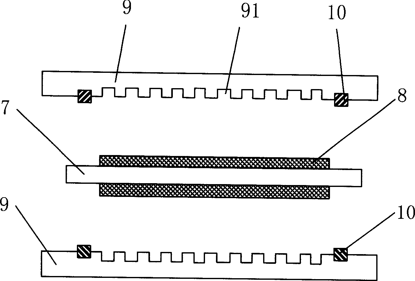
This sealing design has the following disadvantages: 1) the proton exchange membrane 7 will extend to the outside of the sealing gasket 10, so the consumption of the proton exchange membrane is large, resulting in high battery cost; The contact and extrusion of the electrode plate 9 will easily cause the proton exchange membrane to age and crack for a long time, which will easily lead to the danger of mixing the anode gas and cathode gas
However, this kind of sealing device has the following disadvantages: 1) a seal ring is placed on the guide plate, and when the battery is assembled, the protruding seal rings or rigid parts on the two plates squeeze part B mutually, so that the gap between the two plates It is difficult to align neatly, even if the alignment is neat, it is an unstable balance, and misalignment between the two plates is easy to occur; 2) Use a plane or a line to achieve sealing between the sealing ring, and the sealing ring will be damaged after long-term use and aging. Loss of elasticity, thus prone to gas leakage
However, this kind of sealing structure has the following disadvantages: 1) Since the sealing gasket is inserted between the separator plate and the membrane-electrode assembly, it is difficult to align the two separator plates neatly, and even if they are aligned, misalignment is prone to occur; 2) the sealing There is also a line or surface contact between the gasket and the separator, and after long-term use, it will also cause the aging of the gasket to fail and cause gas leakage

Method used


Image

  • Sealing device of proton exchanging film fuel cell unit
  • Sealing device of proton exchanging film fuel cell unit
  • Sealing device of proton exchanging film fuel cell unit

Examples


Embodiment Construction

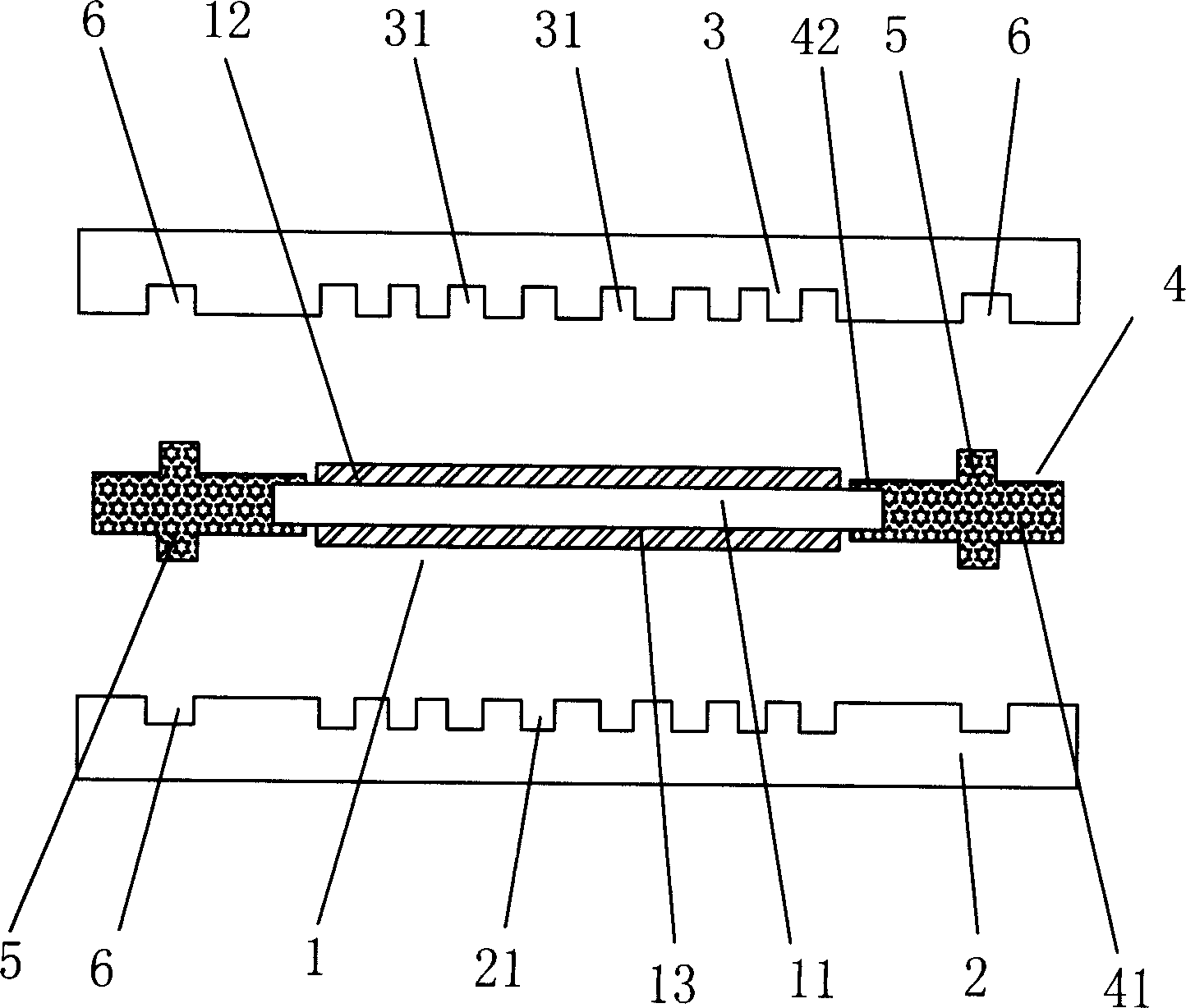
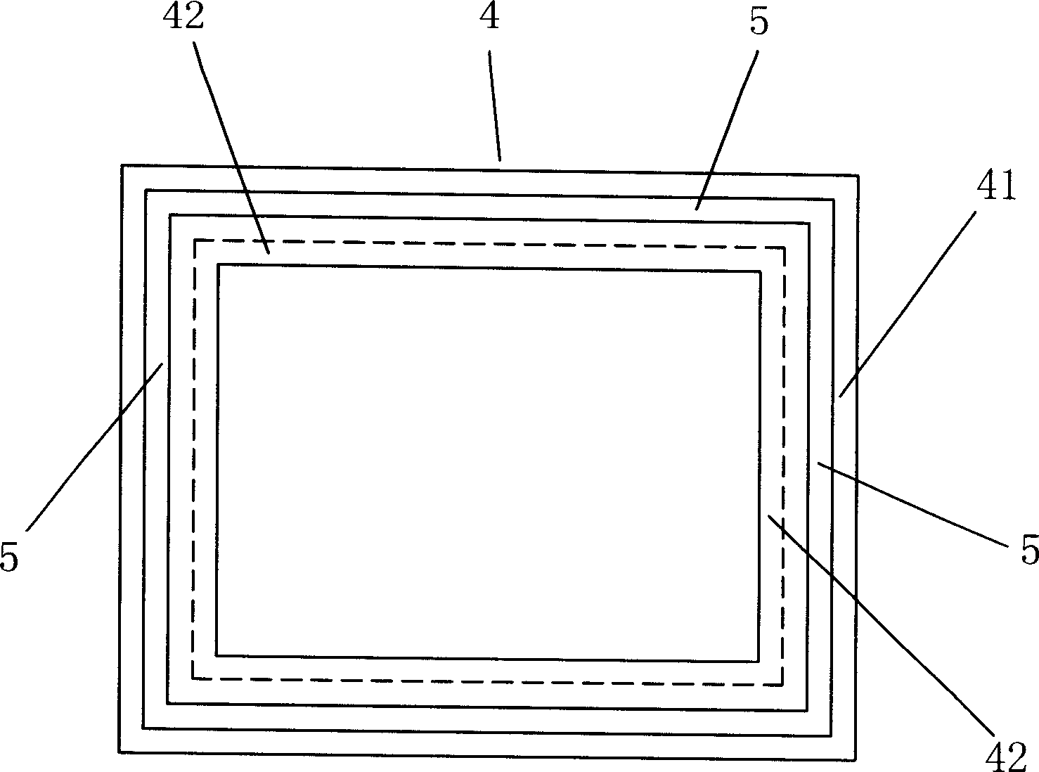
[0026] see Figure 2 to Figure 5 The sealing device of the proton exchange membrane fuel cell unit of the present invention includes a membrane electrode assembly 1 and a cathode guide plate 2 and an anode guide plate 3 sandwiching the membrane electrode assembly. The membrane electrode assembly 1 comprises a proton exchange membrane 11 and a cathode 13 and an anode 12 attached to both sides of the proton exchange membrane 11 in the longitudinal direction. The proton exchange membrane 11 is made of a polymer material, such as the existing DuPont Nafion membrane. The anode 12 and the cathode 13 are all made of porous and conductive materials. In this embodiment, the anode 12 and the cathode 13 are all porous carbon paper or carbon cloth. In the longitudinal direction, the proton exchange membrane 11 It is 0.1%-80% longer than the length of the porous carbon paper or carbon cloth.

[0027] The cathode guide plate 2 and the anode guide plate 3 are provided with several guide gr...


PUM


Abstract

This invented sealing device of a proton exchange film fuel battery unit includes a membrane electrode component, a sealing element, an anode diversion pole plate and a cathode diversion pole plate clamping said membrane electrode component, which includes a proton exchange film and an anode and a cathode adhered at its either side, the sealing element jackets on the circumference of the film and joints with it having a first locating piece facing to the side of the diversion pole plate and a second locating piece matching to and corresponding to the first locating piece is set on the pole plate and the first one is a hump formed from the surface of the sealing element and the second one is a sealing groove formed from the surface of the pole plate facing to the membrane electrode, in which, the two diversion pole plates will not slide due to the design of the two locating pieces.

Description

【Technical field】 [0001] The invention relates to the field of fuel cells, in particular to a sealing device for a proton exchange membrane fuel cell unit. 【Background technique】 [0002] A fuel cell is a reaction device that directly converts chemical energy in fuel and oxidant into electrical energy. Especially for proton exchange membrane fuel cells, it has the advantages of low noise, high energy conversion efficiency, and no environmental pollution. It is an ideal power source in the future. One of them, it can be used for small portable power supply, small household power station or power supply for electric vehicles, etc. [0003] In a fuel cell, there are mainly membrane electrodes, pole plates and sealing units, among which the membrane electrode is the core component of the fuel cell and provides active materials for electrochemical reactions. Gas flow grooves are engraved on the electrode plate to provide the reaction gas flow field, and also provide support for ...

Claims


Application Information

Patent Timeline
Patent Type & Authority Applications(China)
IPC IPC(8): H01M8/10
CPCH01M8/0234H01M8/0273H01M8/0276H01M8/0284H01M8/242H01M2008/1095Y02E60/50
Inventor 张日清刘瑞董俊卿
Owner BYD CO LTD
Learn More