Tunable laser

一种调谐激光器、光反射器的技术,应用在激光器、激光器零部件、半导体激光器等方向,达到低模块成本、简单设置、高性能的效果

Inactive Publication Date: 2006-11-15
NEC CORP
View PDF0 Cites 21 Cited by
  • Summary
  • Abstract
  • Description
  • Claims
  • Application Information

AI Technical Summary

Problems solved by technology

[0012] The object of the present invention is to provide a tunable laser that can solve the problems of conventional tunable lasers, has high reliability, high performance and low cost, and has a simple setting for monitoring the wavelength

Method used


Image

  • Tunable laser
  • Tunable laser
  • Tunable laser

Examples


Embodiment Construction

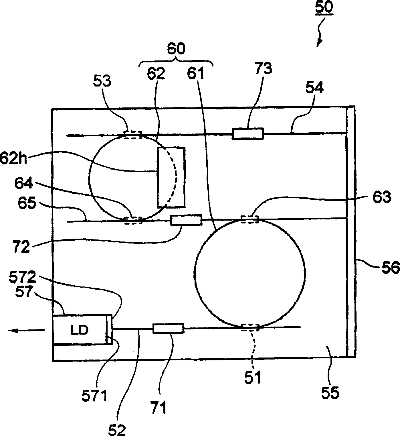
[0036] Such as figure 1 As shown, a tunable laser 50 according to a first embodiment of the present invention has a PLC substrate 55 on which a multi-ring resonator 60 , an input / output side waveguide 52 and a reflection side waveguide 54 are disposed. The multi-ring resonator 60 includes two ring resonators 61, 62 respectively having ring waveguides and different optical paths. The ring resonators 61 , 62 are coupled to each other through directional couplers 63 , 64 and a coupling waveguide 65 , thereby forming the multi-ring resonator 50 . One end of the input / output side waveguide 52 is coupled to the ring resonator 61 through the directional coupler 51 . One end of the reflection-side waveguide 54 is coupled to the ring resonator 62 through the directional coupler 53 . The other end of the reflection-side waveguide 54 extends to one end of a PLC substrate 55 on which a high reflection film 56 as a light reflector is placed. Therefore, the high reflection film 56 is loc...


PUM


Abstract

A tunable laser has a multiple ring resonator comprising a plurality of ring resonators having respective ring-shaped waveguides and respective different optical path lengths, an input / output side optical waveguide coupled to the multiple ring resonator, an optical input / output device such as a laser diode coupled to the input / output side optical waveguide, a reflection side optical waveguide coupled to the multiple ring resonator, an optical reflector coupled to the reflection side optical waveguide for removing light at an unwanted wavelength and reflecting light at a required wavelength, and a wavelength varying mechanism for changing the resonant wavelength of the multiple ring resonator.

Description

technical field [0001] The invention relates to a tunable laser whose oscillation wavelength can be changed. Background technique [0002] As broadband communication becomes more and more popular, it is attempted to introduce a WDM (Wavelength Division Multiplexing) transmission system capable of communicating with a plurality of different optical wavelengths on a single optical fiber to efficiently use optical fiber transmission paths. In recent years, the use of DWDM (Dense WSD) equipment that multiplexes optical signals of several tens of wavelengths to facilitate higher-speed transmission is increasing. Efforts are underway to commercialize ROADMs (Reconfigurable Optical Add-Drop Multiplexers) for adding or dropping optical signals of desired wavelengths at each node in an optical network. If the ROADM system is introduced into the communication environment, the flexibility of the optical network will increase significantly, because they can switch the optical path by c...

Claims


Application Information

Patent Timeline
Patent Type & Authority Applications(China)
IPC IPC(8): H01S5/00G02B6/12G02F1/35H01S3/00H01S3/082H01S3/083H01S5/06H01S5/14
CPCH01S5/02415H01S5/0612H01S5/0654H01S5/0687H01S5/1032H01S5/142H01S5/02325H01S3/10
Inventor 山崎裕幸
Owner NEC CORP
Why Eureka
Try Eureka