
Method for controlling microscopic bubble nucleation in fluid polymer material production and its apparatus

A polymer material, a technology for generating devices, applied in chemical instruments and methods, mixers with rotary stirring devices, mixers, etc. The ratio of the agent and the difficult connection of the non-nuclear segment are difficult to achieve, and the effect of easy control is achieved.

Inactive Publication Date: 2006-11-22
EVERFOCUS WORLDWIDE
View PDF0 Cites 10 Cited by
  • Summary
  • Abstract
  • Description
  • Claims
  • Application Information

AI Technical Summary

Problems solved by technology

[0006] 3. It is not easy to control the separation of the non-nucleating part and the nucleating part of the fluid polymer material heated and melted in the material tube, and it is quite difficult to control the required foaming agent ratio and the connection of the non-nuclear part. often unstable
[0007] The injection port of the foaming agent must be equipped with a check valve to prevent the backflow of the polymer material, but this device will increase the cost and failure rate of the equipment

Method used


Image

  • Method for controlling microscopic bubble nucleation in fluid polymer material production and its apparatus
  • Method for controlling microscopic bubble nucleation in fluid polymer material production and its apparatus
  • Method for controlling microscopic bubble nucleation in fluid polymer material production and its apparatus

Examples


Embodiment Construction

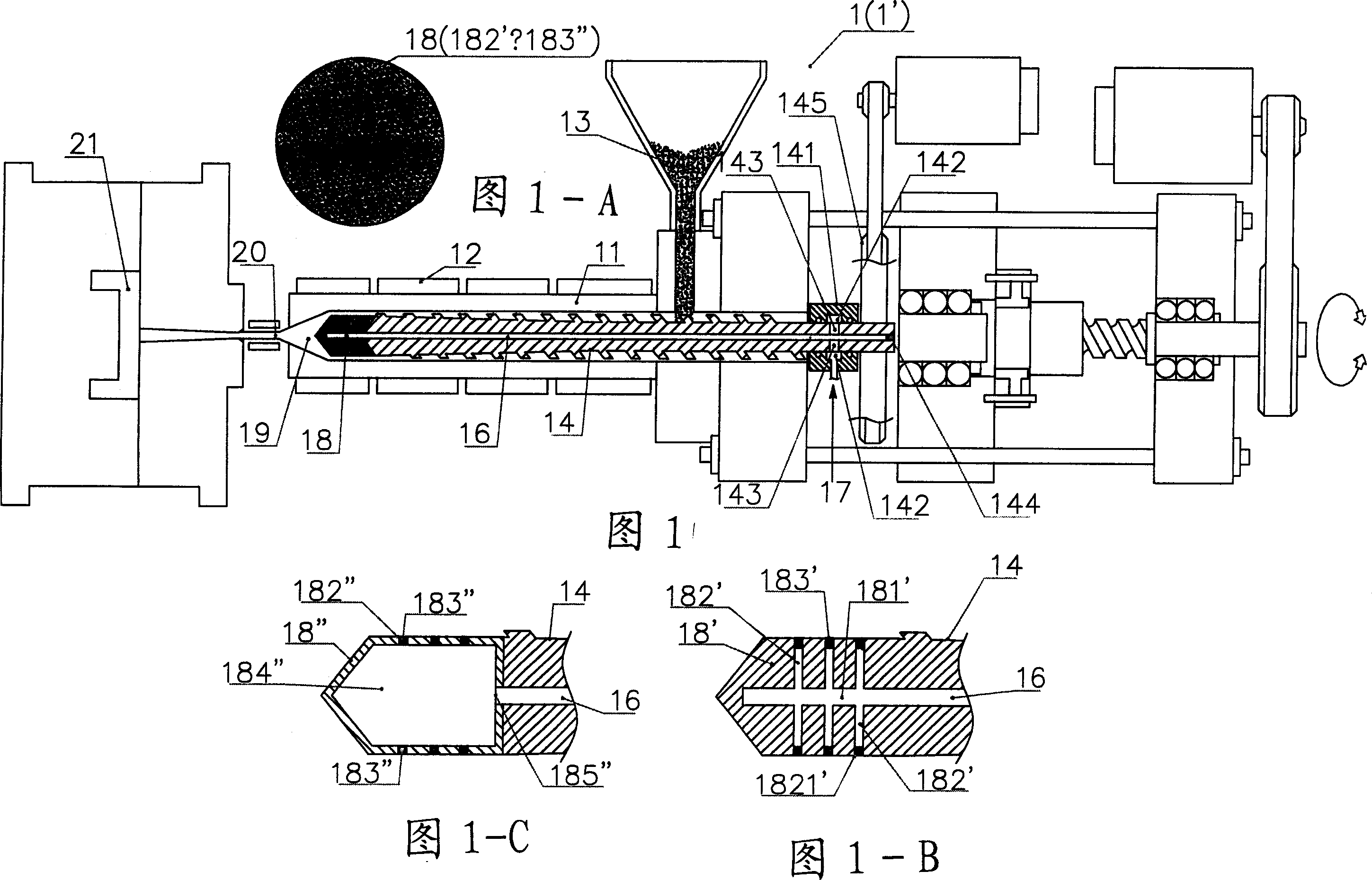
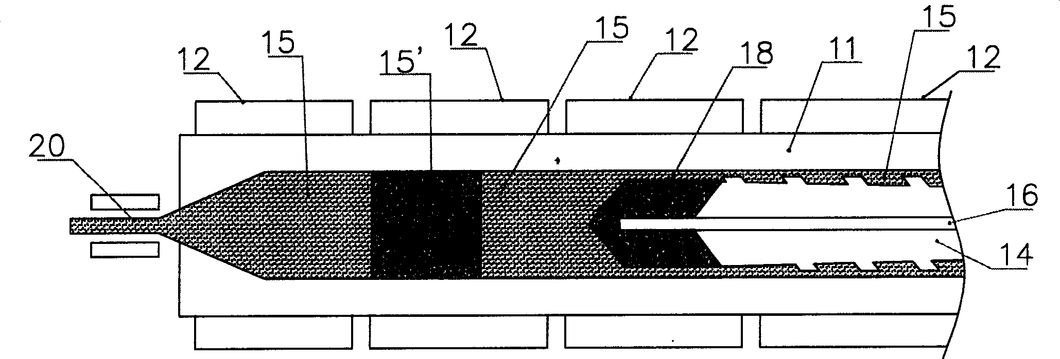
[0033] The first embodiment of the present invention, please refer to FIG. 1 and FIG. 1-A, is to apply a heater 12 installed on the outer edge of the material pipe 11 in the injection or extruder 1, 1' to melt the polymer material 13, and A conveying screw 14 is installed in the material pipe 11, and the molten polymer material 15 is pushed forward by the stirring of the conveying screw 14; and the foaming source is the use of all applicable gases, such as carbon dioxide, nitrogen or other The gaseous source for foaming is used to carry out the foaming reaction of the polymer material; a gas conveying pipe 16 is arranged in the conveying screw 14, and a screw shaft seat 141 is penetrated at the rear end and is fixed on the transmission disc 145, and is connected with a The plug 144 blocks the rear end of the gas delivery pipe 16; the screw shaft seat 141 is provided with an annular air groove 142, and the air inlet 17 communicated with the annular air groove 142 and located in ...


PUM


Abstract

A method for controlling microscopic bubble nucleation in fluid polymer material production and its apparatus that utilizes a gas pipe (16) disposed in the conveyance screw shaft (14) of a conventional injection or extraction forming mechanism and, furthermore, a microbubble generating component (18) (such as a microscopic perforation vented metal head or a microscopic perforation ceramic head, etc.) installed at the front extremity of the conveyance screw shaft (14). At the rear extremity of the gas pipe (16), a pressurization pump or a high pressure gas storage tank is admitted from an air intake opening, enabling the gas to be indirectly heated by an electric heater (12) on the materials pipe (11). The high temperature gas is thereafter outputted from the microscopic perforations of the microbubble generating component (18) such that high temperature microscopic bubbles are directly admitted into the section of liquid polymer material which is then uniformly amalgamated by the conveyance screw shaft (14) and then deposited into a forming die (21). As a result, high pressure gas conveyance or termination is controllable; control is afforded as to whether each section of liquid polymer material is microbubble nucleated and amalgamated. The present invention thereby provides a microbubble nucleation production method in which the non-bubble nucleated is at the surface and the bubble nucleated is at the interior section when the liquid polymer material is poured into a forming die (21).

Description

technical field [0001] The invention relates to a method and a device for generating controllable micro-bubble nuclei in a fluid polymer material. A heater is arranged outside the conveying screw to melt the polymer material in the material pipe, and a heater is arranged inside the conveying screw. A gas conveying pipe connected to the micro-bubble generating component at the front end of the conveying screw, by controlling the high-pressure gas transmission action of the pressurizing pump or the high-pressure gas storage cylinder, to control the formation of bubble nuclei or No bubble core. Background technique [0002] Generally, the polymer material used in the injection or extrusion molding machine is melted into a fluid, by injecting a physical foaming agent into the polymer material, and after stirring, the polymer contains a mixture of foaming agent unit cells, The mixture is then injected into the molding die to solidify, so that the pressure drop in the mixture pro...

Claims


Application Information

Patent Timeline
IPC IPC(8): B29C45/46B29C37/00B29C45/17B29C48/515
CPCB29B7/42B29B7/7414B29C44/3446B29C44/3449B29C44/3469B29C45/1816B29K2105/0005B29C48/29B29C48/022B29C48/03B29C48/286B29C48/53B29C48/515B01F23/2351B01F23/2373B01F27/2122
Inventor 张晋淙
Owner EVERFOCUS WORLDWIDE
Learn More