Bitranslation-rotation parallel mechanism used for parallel motion structure

A parallel and motion technology, applied in manipulators, program-controlled manipulators, metal processing machinery parts, etc., can solve problems such as unfavorable control, small working space, and difficulty in correcting kinematics.

Inactive Publication Date: 2006-11-29
JIANGSU POLYTECHNIC UNIVERSITY
View PDF0 Cites 3 Cited by
  • Summary
  • Abstract
  • Description
  • Claims
  • Application Information

AI Technical Summary

Problems solved by technology

For example, (1) kinematics is difficult to solve; (2) the motion platform pose is a strong coupling of input, which is not conducive to control; (3) the mechanism is complex, so that the work space is small; (4) it is difficult to manufacture high-precision ball pairs Wait

Method used


Image

  • Bitranslation-rotation parallel mechanism used for parallel motion structure

Examples


Embodiment Construction

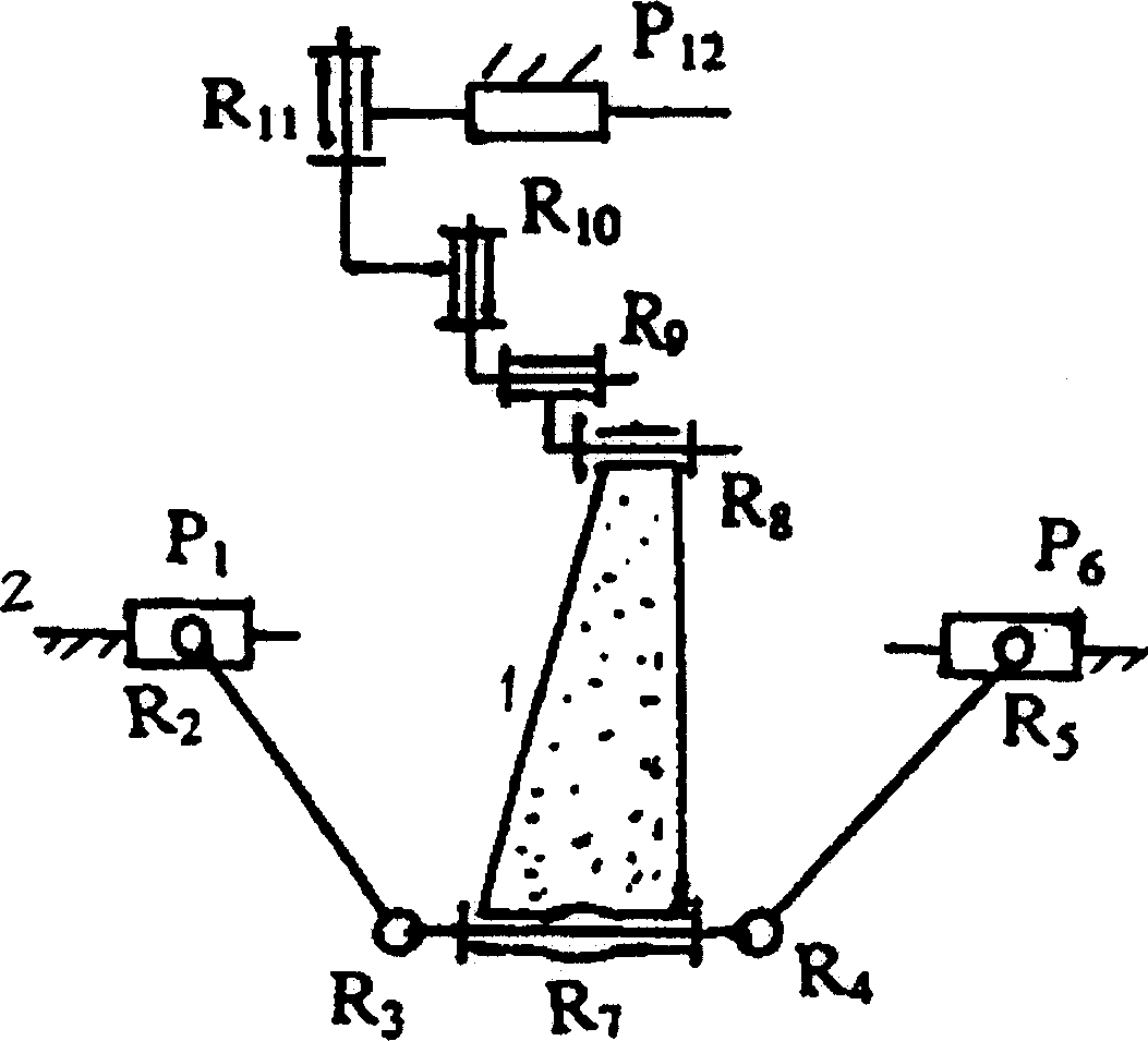
[0007] attached figure 1 The structure shown may also be an embodiment of the invention. It consists of a dynamic platform 1, a static platform 2 and two generalized branches with different structures. The first generalized branch is routed by a mobile pair P 12 , two revolving pairs R that are perpendicular to the moving pair and whose axes are parallel to each other 11 , R 10 and the other two revolving pairs R that are perpendicular to the first two revolving pairs and whose axes are parallel to each other 8 , R 9 formed in series; the second generalized branch consists of 4 revolving pairs R 2 , R 3 , R 4 , R 5 and 2 mobile vice P 1 ,P 6 The 6-bar planar circuit and a mutually perpendicular rotating joint R 7 formed in series. The end components of the two generalized branches are fixedly connected to the dynamic and static platforms respectively, and the two revolving pairs R located on the dynamic platform 7 , R 8 Arranged in parallel with each other, there...


PUM


Abstract

A parallel two-translation one-rotation mechanism for the parallel moving structure has 3-freedom, and is composed of movable platform, static platform, the first generalized branch consisting of a moving set and 4 rotating sets, and the second generalized branch consisting of a 6-rod planar loop comprising 4 rotating sets and bi-translation set, and a rotating set.

Description

technical field [0001] The invention relates to an executive mechanism of parallel motion equipment, specifically, it provides a new type of two-translation-rotation parallel mechanism for virtual-axis numerical control machine tools and parallel robots of parallel structure motion equipment. Background technique [0002] Parallel structure CNC machine tool refers to the machine tool with parallel mechanism as the executive mechanism. This machine tool is considered to be a revolution in the structure of machine tools since the 20th century. At present, prototypes of this machine tool have been developed in the United States, Japan and other countries, and the parallel mechanisms used are all traditional Stewan mechanisms. This mechanism for controlling the position and attitude of the tool in space is mainly composed of a base, a moving platform and a connecting rod. The base and the moving platform are connected by a connecting rod, and the two ends of the connecting rod a...

Claims


Application Information

Patent Timeline
Patent Type & Authority Applications(China)
IPC IPC(8): B23Q1/48B25J9/10B25J9/08
Inventor 沈惠平杨廷力
Owner JIANGSU POLYTECHNIC UNIVERSITY
Why Eureka
Try Eureka