Self-operated method and system for removing group of bottle from container

A self-supporting, self-gravity technology, applied in the direction of packaging bottles, packaging, packaging items, etc., can solve the problems of increased power consumption and air consumption, mechanical wear, high center of gravity, etc., to save working time, reduce mechanical wear, fast falling effect

Inactive Publication Date: 2006-11-29
刘宝玉
View PDF0 Cites 9 Cited by
  • Summary
  • Abstract
  • Description
  • Claims
  • Application Information

AI Technical Summary

Problems solved by technology

Due to the light weight and high center of gravity of containers such as empty beer bottles and beverage bottles, and in most beer and beverage production enterprises, the vertical deviation between the central axis of the bottle and the bottom of the bottle, and the deviation of the size and shape of the box The range is very large, and the bottle grabber or clamping mechanism of the unloader frequently resists the container mouth or the box mouth, causing malfunction and shutdown
In the prior art, the operation process of the bottle grabber or clamping mechanism of the unloader has the following disadvantages: one, because it is forced to land on the items to be unloaded in the box, if it is pushed against the box or box The container cannot be stopped immediately, but it has to wait until the clamping mechanism is lifted to a certain height and the corresponding sensor is turned on to send a parking command to the driving mechanism such as the motor before stopping. At this time, machinery, boxes or The damage of the clamped items is time-consuming and labor-intensive to solve, and even affects the production speed of the entire production line
Second, the clamping mechanism has to be lifted up and down twice in a working cycle of unloading, which not only wastes the necessary working time, but also causes unnecessary mechanical wear
3. When the bottle is transported horizontally, the power mechanism forcibly drives the clamping mechanism and its clamped items throughout the whole process. The terminal braking wastes energy and causes mechanical wear. At the same time, the clamped containers will swing and collide with each other.
In order to match the production speed of the whole line equipment, equipment manufacturers have to design the unloading machine as a multi-box machine that can unload three, four, five, six or even eight or ten boxes at a time. The structure of the machine has become very complicated, difficult to manufacture, high in cost and price, and increased in power and air consumption during use. At the same time, it has also brought multiple turnover boxes and multiple bottles, multiple grasping or clamping devices and multiple It is even more difficult to align the bottles accurately. During the use, the bottle and the box, the grasper or the bottle clamper and the bottle are frequently pressed against each other, which will damage the machine, the box, and the bottle. Many users cannot afford or dare not use the unloader. box machine
[0004] In the patent or patent application documents of the previous patent application "special technical scheme for the operation of the unloading machine", "box lifting mechanism", "a self-operated operation method and system of a clamping mechanism" and "dropping box device" , all involve a kind of unpacking scheme that clamps the bottle and then falls off the empty box. Compared with the prior art, these unpacking schemes have made significant progress, and have solved the above-mentioned problems and drawbacks from different angles and degrees. After further research and experiments, it was found that when the box is completely separated from the container held by the clamping mechanism by automatically falling off the box, the scheme of horizontally moving the clamping mechanism and the container it holds still has certain limitations. , in some cases, the unloading speed has to be slowed down due to the restriction of bottle pouring factors

Method used


Image

  • Self-operated method and system for removing group of bottle from container
  • Self-operated method and system for removing group of bottle from container
  • Self-operated method and system for removing group of bottle from container

Examples


Embodiment Construction

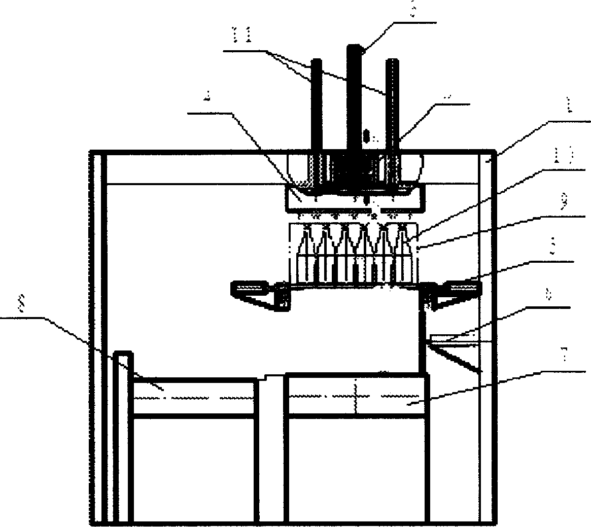
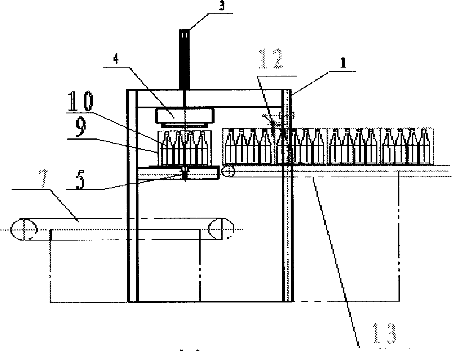
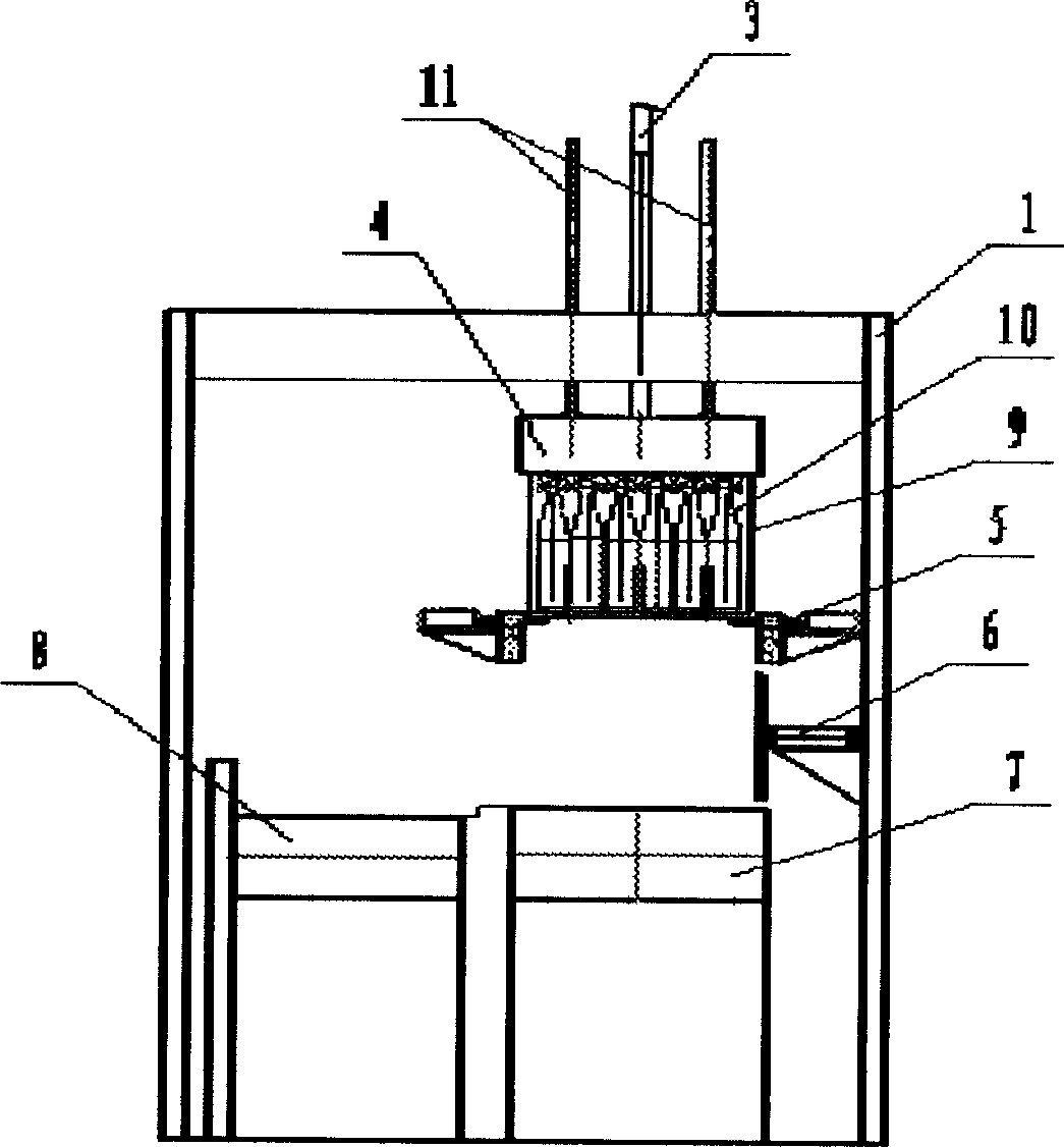
[0028] like Figure 1 to Figure 9As shown, in the initial state, the clamping mechanism 4 is located at a high position due to the lifting power or supporting force of the lifting device 3, and the box 9 carrying the container 10 to be unloaded enters the drop box device 5 directly below the clamping mechanism 4 After reaching the predetermined position on the top, the lifting device 3 releases the lifting power or supporting force to the clamping mechanism 4, so that the latter falls on the predetermined position on the container 10 to be unloaded in the box by its own weight and clamps the container 10. At the same time, the clamping Mechanism 4 is once again suspended at this position by a supporting force of lifting device 3; after container 10 is clamped, at first the container 10 is completely separated from the box 9 by automatically falling off the empty box 9, and the container 10 is completely separated from the box 9 by pushing the empty box mechanism 6. Case 9 push...


PUM


Abstract

An autonomous case unloading method and system for separating a container from its packing case is disclosed. Said method includes such steps as moving said packing case to a position under clamping unit, dropping the clamping unit down to a predefined position by its dead weight, clamping the container in said case, dropping the case down to separate it from the container, moving the case onto its output unit, dropping the clamping unit along with container down to a container output unit by their dead weight, and releasing the container.

Description

technical field [0001] The invention relates to a self-powered box unloading method and system, in particular to a self-powered box unloading method and system for a box unloading machine. technical background [0002] The unloading machine is mainly used in the production lines of beer, beverage and condiment industries to take out empty containers from the turnover boxes and place them on the container conveying line and the case conveying line respectively. Due to the light weight and high center of gravity of containers such as empty beer bottles and beverage bottles, and in most beer and beverage production enterprises, the vertical deviation between the central axis of the bottle and the bottom of the bottle, and the deviation of the size and shape of the box The range is very large, and the bottle grabber or clamping mechanism of the unpacking machine frequently resists the container mouth or the box mouth, resulting in malfunction and ...

Claims


Application Information

Patent Timeline
Patent Type & Authority Applications(China)
IPC IPC(8): B65B21/14B65B69/00
Inventor 刘宝玉
Owner 刘宝玉
Why Eureka
Try Eureka