

Paper money banding machine
A technology for binding machines and banknotes, which is applied in the directions of binding materials, packaging of paper products, types of packaging items, etc., can solve the problems of complex and large-scale structure and increase in cost, and achieve the effect of simple structure and reduction of manufacturing cost.
- Summary
- Abstract
- Description
- Claims
- Application Information
AI Technical Summary
Problems solved by technology
Method used
Image

Examples
Embodiment Construction
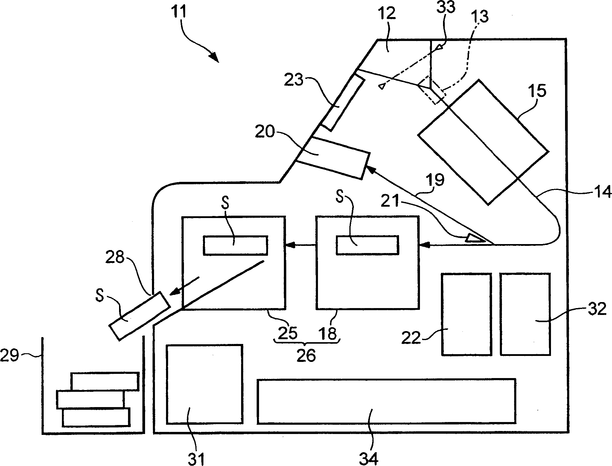
[0026] Hereinafter, a banknote binding machine according to an embodiment of the present invention will be described with reference to the drawings.
[0027] The banknote binding machine 11 of the present embodiment is a binding machine specialized in binding, such as figure 1 As shown in the schematic structure shown in , it includes: being arranged on the upper side of the front side (operator side) of the machine body, the banknote insertion port 12 (injection part) where loose banknotes are dropped from the outside of the machine; Rear side, the delivery unit 13 that separates and sends out the banknotes put into the banknote insertion opening 12 one by one; the delivery unit 14 that transports the banknotes sent out by the delivery unit 13; 14 Identification section 15 for banknotes conveyed.
[0028] Loose banknotes are inserted into the banknote insertion port 12 in a state in which the longitudinal direction is along the left-right direction of the machine body. The ...
PUM
 Abstract
Description
Claims
Application Information