
Pump

A technology for pump chambers and casings, applied in pumps, pump devices, pump components, etc., can solve problems such as cracks and water leakage in the pump 100, and achieve the effects of increasing durability, improving water pressure resistance, and eliminating water leakage

Inactive Publication Date: 2010-12-15
NIDEC SHIBAURA ZHEJIANG
View PDF7 Cites 0 Cited by
  • Summary
  • Abstract
  • Description
  • Claims
  • Application Information

AI Technical Summary

Problems solved by technology

Due to this repeated expansion, it is easy to generate cracks on at least a part of the weld seam where the strength of the casing is weak, thereby causing a problem that the pump 100 leaks water.

Method used


Image

  • Pump
  • Pump
  • Pump

Examples


no. 1 approach

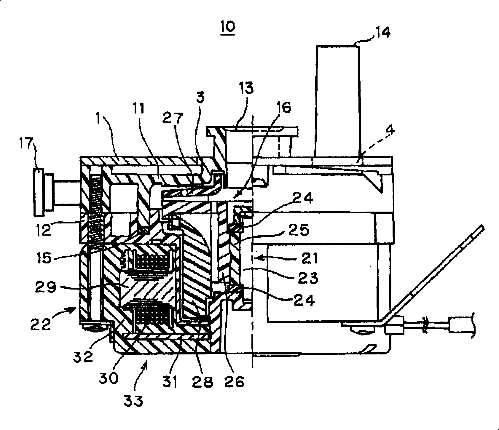
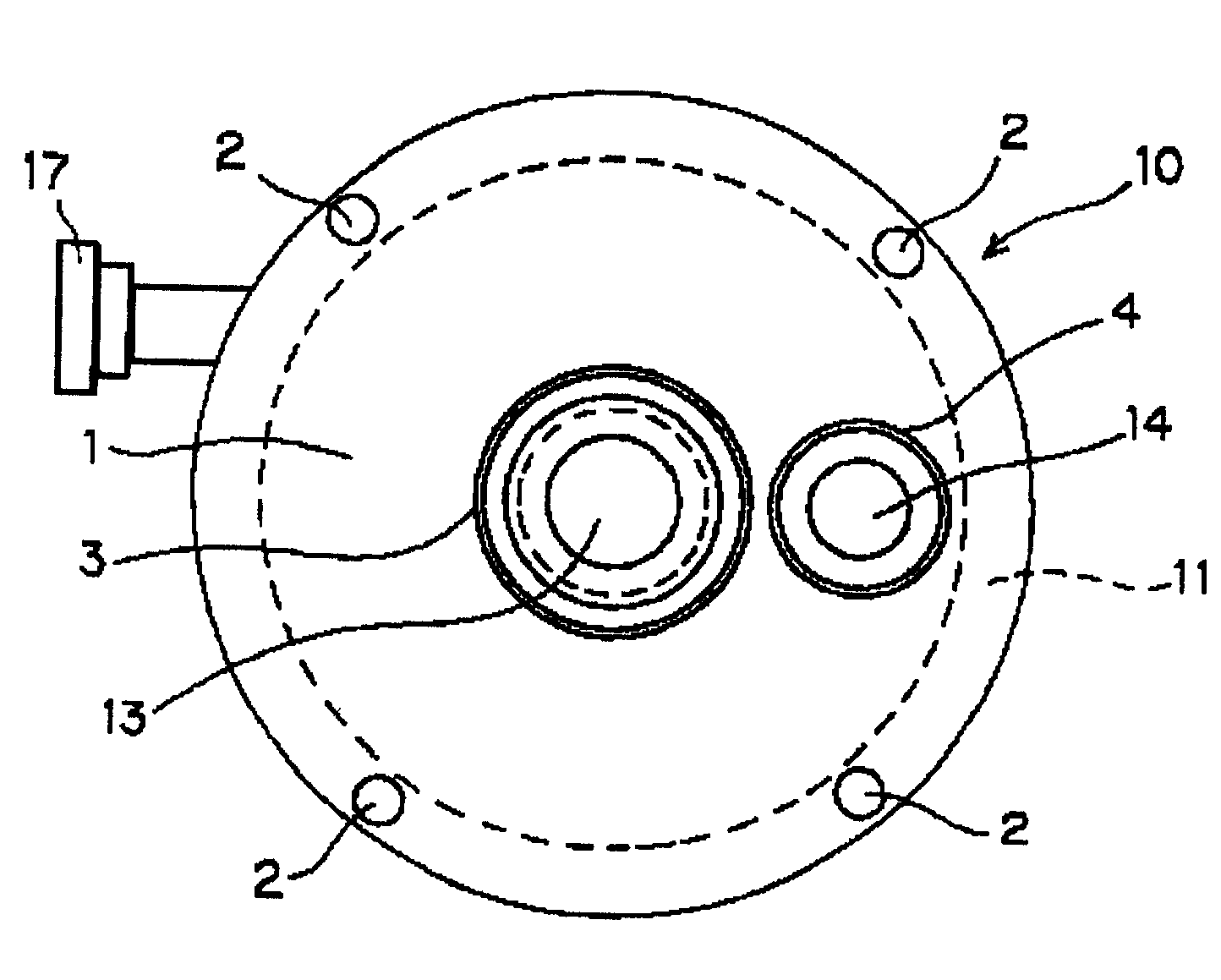
[0035] figure 1 is a longitudinal half-sectional view showing the pump 10 of the first embodiment; figure 2 is its top view. Such as figure 1 , 2 As shown, the pump 10 is a waterproof pump, and the rotor 21 is arranged inside the casing between the upper and lower casings 11 and 12 made of synthetic resin, and a ring is arranged along the outer periphery of the rotor 21. Shaped stator 22, thereby constituting the motor of the pump 10.

[0036] The upper and lower casings 11, 12 seal the inside of the pump 10 with packing 15 in between. The pump chamber 16 is arranged in the upper space in the casing. 14 protrudes from the housing 11 and is integrally formed with the housing 11 .

[0037] The rotor 21 is rotatably supported on a fixed shaft 23 at the center of the pump 10 inside the casing via a rotating shaft 25 and thrust washers 24 arranged above and below the rotating shaft 25, and the fixed shaft 23 is fixed on the upper , Between the lower housing 11,12.

[0038...

no. 2 approach

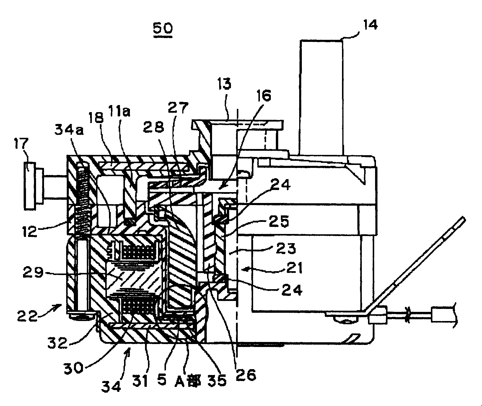
[0048] image 3 It is a half sectional view showing the pump 50 of the second embodiment, Figure 4 yes image 3 Enlarged view of part A in . Such as image 3 , Figure 4 As shown, the pump 50 is a waterproof pump having the same main structure as the pump 10 in the first embodiment. exist image 3 , for the same components as given with figure 1 The same reference numerals are used, and the description of the structure of the pump 50 is omitted.

[0049] In the pump 50 of the second embodiment, the stator 22 constituted by the annular laminated iron core 29 and the winding 30 is molded together with the printed circuit board 31 in the molding resin 32, thereby forming an annular resin molding. body34.

[0050] The resin molded body 34 is embedded with a ring-shaped molded part of the molded resin 32a between the base plate 31 on the outside of the cup-shaped bottom 35 of the case 12 and a part of the contact part with the case 12, that is, the part of the molded resi...


PUM


Abstract

This invention provides a pump, which can increase the intensity of the pump with resin casing, improve the water pressure resistance and durability, without increasing the pump cost and weight. The motor of this invented pump(10) comprises: the rotor(21) is installed inside the pump(10) resin casing(11, 12) having a water inlet(13) and a water outlet(17); the stator(22) is molded inside the molding resin(32), so as to form the circular resin shaped body(33), which is on the outer side of the said casing(12) and arranged on the outer peripheral part of the said rotor(21); the vanes(27) connected with the said rotor(21) are installed inside the pump chamber(16) inside the casing; on the outer surface of the said casing(11) secures a metal support bracket(1) that covers this casing(11).

Description

technical field [0001] The present invention relates to a pump, and more specifically, to a pump in which the strength of the outside and inside of a pump made of a synthetic resin casing is increased, and water pressure resistance is improved. Background technique [0002] For pumps incorporated in equipment such as hot water supply systems, the pump itself is also required to be smaller, lighter, and more energy efficient in response to the need for smaller, lighter, and energy-saving equipment. [0003] As such a pump, the rotor is sealed inside the casing, the stator for driving the above-mentioned rotor is arranged outside the above-mentioned casing to constitute a DC brushless motor, and the impeller is arranged in the pump chamber connected to the rotor (for example, patent Literature 1). [0004] Figure 7 It is a vertical half cross-sectional view showing an example of a conventional pump. Such as Figure 7 As shown, the pump 100 is a waterproof pump (キャンドイイプのポンプ)...

Claims


Application Information

Patent Timeline
Patent Type & Authority Patents(China)
IPC IPC(8): F04D13/06F04D29/02F04D29/42
CPCF04D13/064F04D29/007F04D29/026F04D29/406F04D29/445F05D2210/11F05D2300/10F05D2300/43F16B5/02Y10S415/00
Inventor 泽崎基川岛丈典西村胜史
Owner NIDEC SHIBAURA ZHEJIANG
Learn More