

Distance gate type laser 3D imaging radar system
An imaging radar and general-type technology, which is applied in the radio wave measurement system, electromagnetic wave re-radiation, utilization of re-radiation, etc., can solve the problems of blurred distance image and short action distance, and achieve easy implementation, strong device versatility, and long-distance high resolution effects
- Summary
- Abstract
- Description
- Claims
- Application Information
AI Technical Summary
Problems solved by technology
Method used
Image

Examples
specific Embodiment approach 1
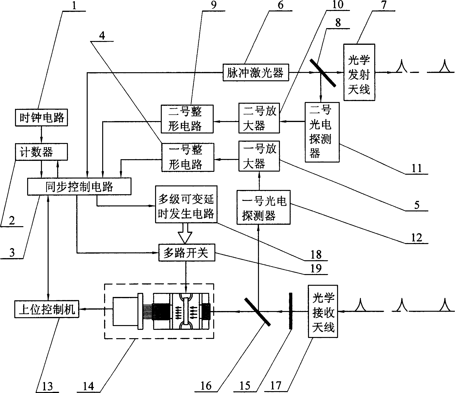
[0008] Specific implementation mode one: see figure 1 , the radar system of this specific embodiment is made up of pulsed laser 6, optical transmitting antenna 7, synchronous control circuit 3, multistage variable delay generation circuit 18, multi-way switch 19, gating type ICCD 14, optical filter 15, optical The receiving antenna 17 is composed of the host controller 13. The beam emitted by the pulse laser 6 is shaped by the optical transmitting antenna 7 and then irradiated on the target. The echo beam reflected by the target is shaped and converged by the optical receiving antenna 17 and reaches the filter 15. The optical input end of the optical input port, the light beam output from the optical output end of the optical filter 15 is incident on the optical input end of the gating type ICCD 14, and the image information output end of the gating type ICCD 14 is connected to the image information input end of the host controller 13, The delay control end of the synchronous ...
specific Embodiment approach 2
[0009] Specific implementation mode two: see figure 1 The difference between this embodiment and Embodiment 1 is that the imaging device also includes a first beam splitter 8, a No. 2 shaping circuit 9, a No. 2 amplifier 10, and a No. 2 photodetector 11. The first beam splitter 8 Located between the output end of the pulsed laser 6 and the input end of the optical transmitting antenna 7, part of the light beam emitted by the pulsed laser 6 is incident on the input end of the optical transmitting antenna 7 after being split by the first beam splitter 8, and the other part is incident on the optical transmitting antenna 7. The photosensitive end of No. photodetector 11, the electrical signal output end of No. 2 photodetector 11 connects the input end of No. 2 amplifier 10, the output end of No. 2 amplifier 10 connects the input end of No. 2 shaping circuit 9, No. 2 shaping circuit The output end of 9 is connected to the initial launch time input end of the synchronous control ci...
specific Embodiment approach 3
[0010] Specific implementation mode three: see figure 1 The difference between this specific embodiment and the second specific embodiment is: the imaging device also includes a second beam splitter 16, a No. 1 photodetector 12, a No. 1 amplifier 5 and a No. 1 shaping circuit 4, and the second beam splitter 16 Located between the optical output end of the optical filter 15 and the optical input end of the gate-type ICCD 14, part of the light output from the optical output end of the optical filter 15 is incident on the gate-type ICCD after being split by the second beam splitter 16 The light input end of 14, the other part is incident on the photosensitive end of No. 1 photodetector 12, the output end of No. 1 photodetector 12 is connected the input end of No. 1 amplifier 5, and the output end of No. 1 amplifier 5 is connected No. 1 shaping circuit 4, and the output of the No. 1 shaping circuit 4 is connected to the initial receiving time input of the synchronous control circu...
PUM
 Abstract
Description
Claims
Application Information