Radio voting system

A voting system and wireless technology, applied in the field of wireless electronic voting system, can solve the problems of single function, insufficient transmission distance, high bit error rate, etc., achieve strong anti-interference ability, improve conference efficiency, and low bit error rate.

Inactive Publication Date: 2006-11-29
CAS OF CHENGDU INFORMATION TECH CO LTD
View PDF0 Cites 0 Cited by
  • Summary
  • Abstract
  • Description
  • Claims
  • Application Information

AI Technical Summary

Problems solved by technology

[0003] The purpose of the present invention is to overcome the shortcomings of the existing wireless electronic voting system, such as high bit error rate, insufficient transmission distance, single function, etc., and provide a wireless electronic v

Method used


Image

  • Radio voting system
  • Radio voting system
  • Radio voting system

Examples


Embodiment Construction

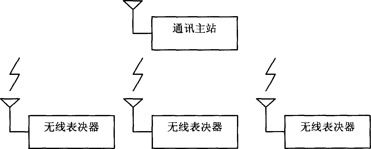
[0044] Further describe technical scheme of the present invention below in conjunction with accompanying drawing: figure 1 It is a wireless voting system including a minimum system configuration unit, the minimum system configuration unit includes a communication master station and at least one wireless voting device (three wireless voting devices), the wireless voting device is connected to the communication master station through a wireless line, On the master station, there are rights management, system parameter configuration, association table management, proposal management, system testing, voting / review / scoring processing, display control, underlying communication management, voting device control management, printing management, history record query management , database access and check-in information query program modules.

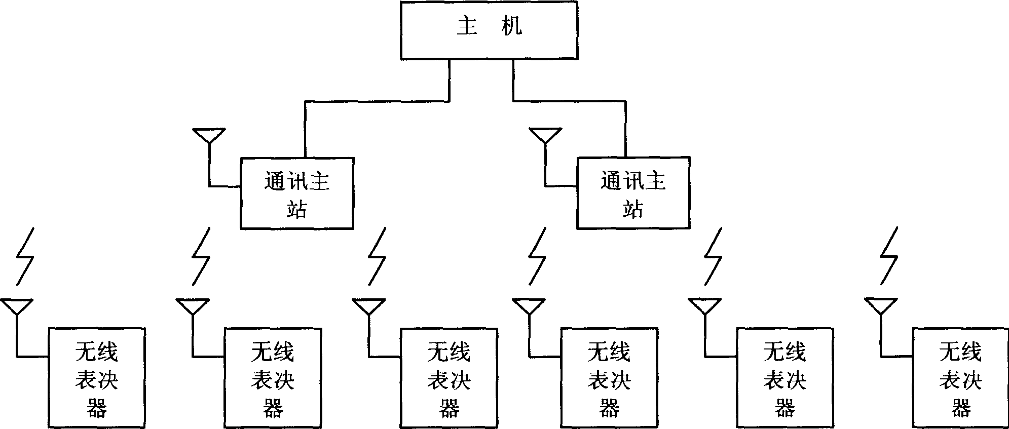
[0045] figure 2 It is a wireless voting system including a host computer and two minimum system configuration units. The minimum system config...


PUM


Abstract

A radio voting system comprises a host and a minimum system configuration unit including a communication main station and at least one voter formed by shell and internal control circuit. It is featured as setting voting keyboard, digital key, display screen, cover and indication lamp on panel of shell, connecting them separately to internal control circuit, connecting cover with shell through leaflet and operating vote master control software on host.

Description

technical field [0001] The invention relates to an electronic voting system, in particular to a wireless electronic voting system. technical background [0002] State agencies, enterprises and institutions hold various meetings regularly or irregularly, some of which may involve voting matters. In order to improve the efficiency of meeting voting and the accuracy of vote counting, more and more electronic voting systems are used. The electronic voting system is technically divided into wireless electronic voting and wired electronic voting. In some occasions, such as holding a meeting in a temporary meeting place, it is very difficult to rebuild and use the wired electronic voting system. At this time, wireless electronic voting The system shows great advantages. But the existing wireless electronic voting system has high bit error rate, insufficient transmission distance and single function. Contents of the invention [0003] The purpose of the present invention is to o...

Claims


Application Information

Patent Timeline
IPC IPC(8): G07C13/00
Inventor 李永华崔喆唐雪梅
Owner CAS OF CHENGDU INFORMATION TECH CO LTD
Why Eureka
Try Eureka