
Plasma display device

A display device, plasma technology, applied in identification devices, static indicators, instruments, etc., can solve the problem of driving efficiency decline, and achieve the effects of shortening delay time, improving durability, and improving driving efficiency

Inactive Publication Date: 2006-11-29
LG ELECTRONICS(NANJING) PLASMA CO LTD
View PDF0 Cites 2 Cited by
  • Summary
  • Abstract
  • Description
  • Claims
  • Application Information

AI Technical Summary

Problems solved by technology

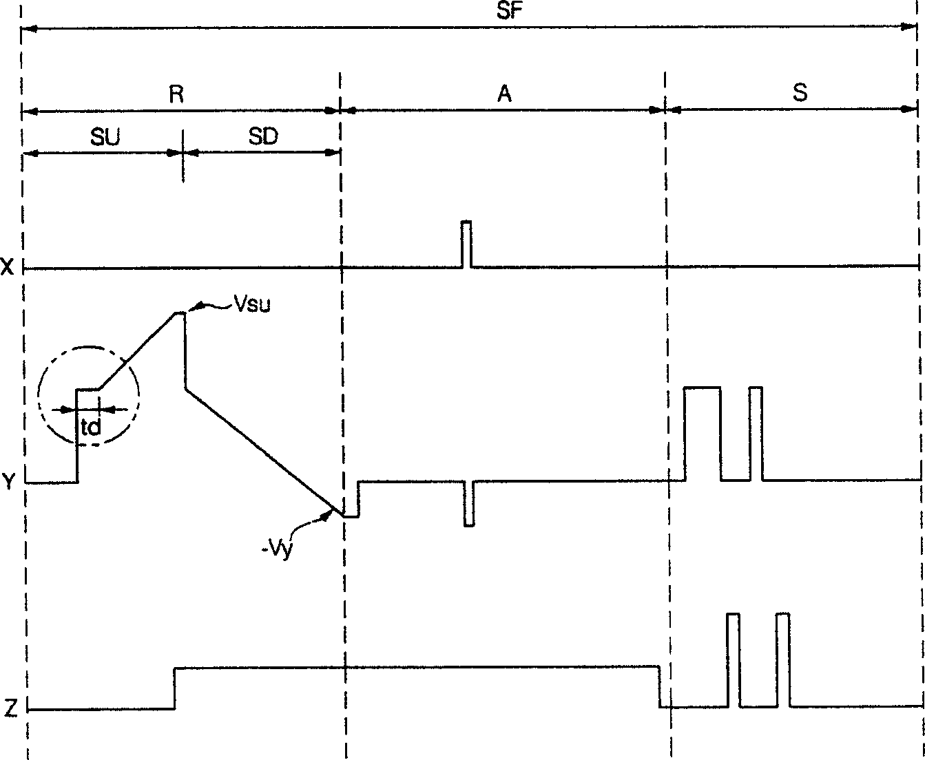
[0015] That is, in the prior art, a time delay inevitably occurs within the adjustment time (td) required to keep the voltages of the Drain terminal and the Source terminal of the third switch at the same level. Therefore, as figure 2 As shown, the time delay (td) from when the third switch is turned on and enters the rising edge interval to when the rising edge signal rises will result in a decrease in driving efficiency

Method used


Image

  • Plasma display device
  • Plasma display device
  • Plasma display device

Examples


Embodiment Construction

[0032] Hereinafter, preferred embodiments are given, and detailed descriptions are given in conjunction with the accompanying drawings.

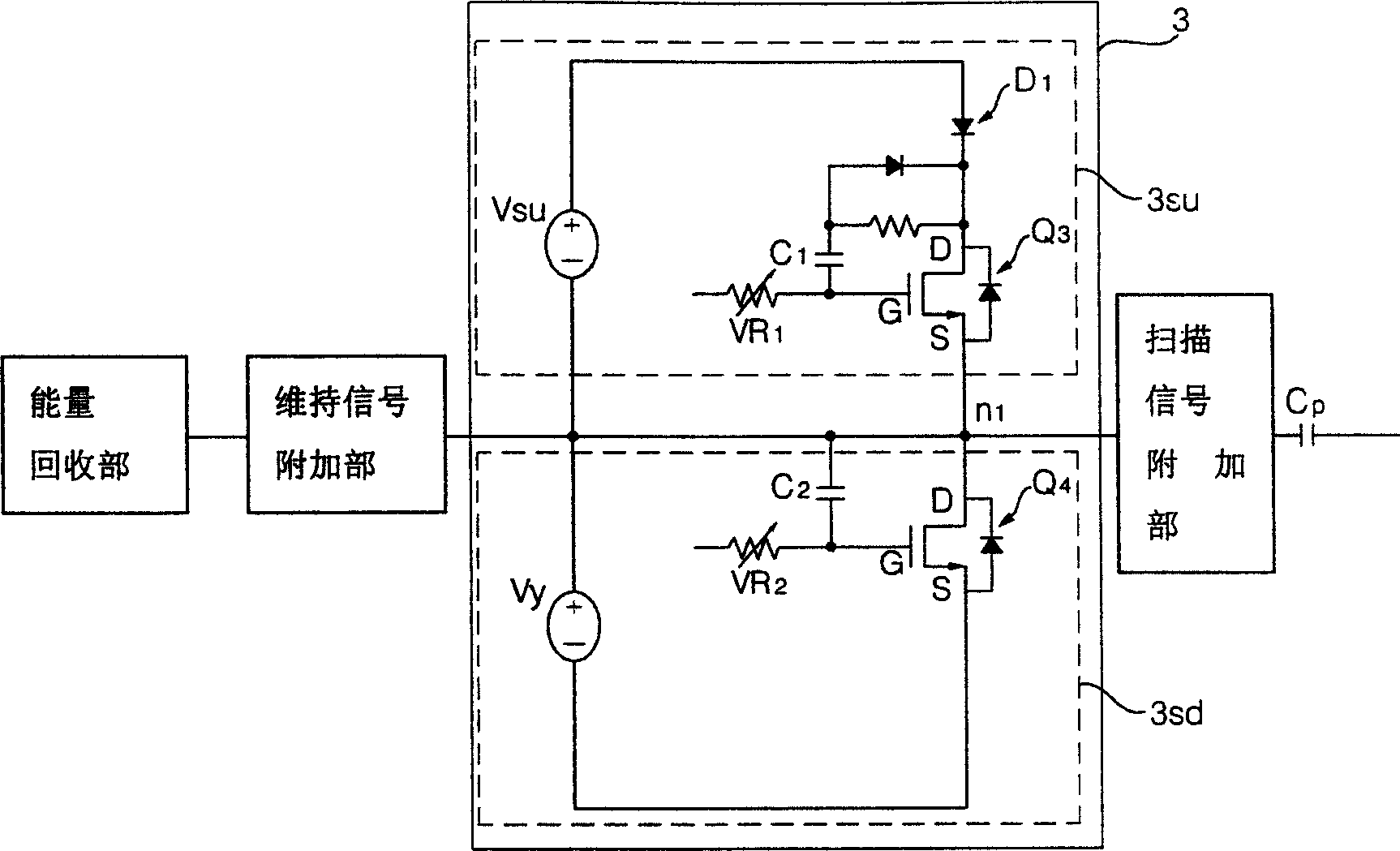
[0033] Figure 4 It is a circuit diagram of the plasma display device in the present invention, and FIG. 5 is a rising edge signal waveform diagram of the plasma display device in the present invention. The contents of the present invention will be described in detail with reference to the above-mentioned drawings.

[0034] First, the energy recovery unit 10 charges the Panel Capacitor (Cp) to the maintenance voltage and then discharges it during the maintenance period. In order to minimize the loss caused by the invalid voltage generated during this process, the energy recovery unit is connected to the maintenance signal addition unit 20 described below. .

[0035] Therefore, the energy recovery unit 10 includes an oscillator that forms an LC resonance circuit together with the Panel Capacitor (Cp), and a Source Capacitor that stores ener...


PUM


Abstract

A plasma display panel device is provided to enhance driving efficiency by reducing a time delay for raising a set-up signal in a set-up period and to improve durability of a driving circuit by reducing heat generation of a switch. A plasma display panel device includes a set-up signal application unit(30su). The set-up signal application unit includes a discharge path from a Miller capacitor connected with a control terminal of a switch for applying a ramp waveform signal to a voltage source. A capacitor for protecting the voltage source is connected in parallel to the voltage source. A path blocking element is serially connected with a third switch in order to block the path toward the voltage source.

Description

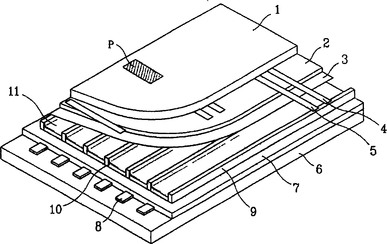
1. Technical field [0001] The present invention relates to a plasma display device, in particular to a plasma display device which can shorten the delay time of a rising edge signal in the rising edge interval and improve driving efficiency. 2. Background technology [0002] Recently developed flat panel display devices include liquid crystal display (liquid crystal display; LCD), field emission display (field emission display; FED), plasma display panel (plasma display panel; PDP) and the like. Among them, the PDP has higher luminance and luminous efficiency and a wider viewing angle than other flat-panel display devices, and has attracted much attention as a large-scale display device. [0003] figure 1 is a partial schematic diagram of a plasma display panel, figure 2 It is a driving waveform diagram of a plasma display panel. [0004] First, the scan electrodes 4 and the sustain electrodes 6 covered by the dielectric layer 2 and the protective film 3 are mounted symm...

Claims


Application Information

Patent Timeline
IPC IPC(8): G09F9/313G09G3/28G09G3/296
CPCG09G3/2927G09G3/2965G09G2310/061G09G2330/023G09G2330/045
Inventor 朴現一
Owner LG ELECTRONICS(NANJING) PLASMA CO LTD
Learn More