Freezing apparatus

A technology of freezing device and feeding device, which is applied to household refrigeration devices, coolers, lighting and heating equipment, etc., can solve the problems of high assembly cost, unfavorable reciprocating vibration, large vibration acceleration, etc., and is conducive to popularization and application. The effect of high vibration acceleration and high vibration efficiency

Active Publication Date: 2006-12-06
SIFANG TECH GRP CO LTD
View PDF0 Cites 18 Cited by
  • Summary
  • Abstract
  • Description
  • Claims
  • Application Information

AI Technical Summary

Problems solved by technology

However, the reciprocating vibration and feed of the existing circulating conveying mesh belt are driven by the servo motor system. Since the drive requires large vibration acceleration and large output tor

Method used


Image

  • Freezing apparatus
  • Freezing apparatus
  • Freezing apparatus

Examples


Embodiment 1

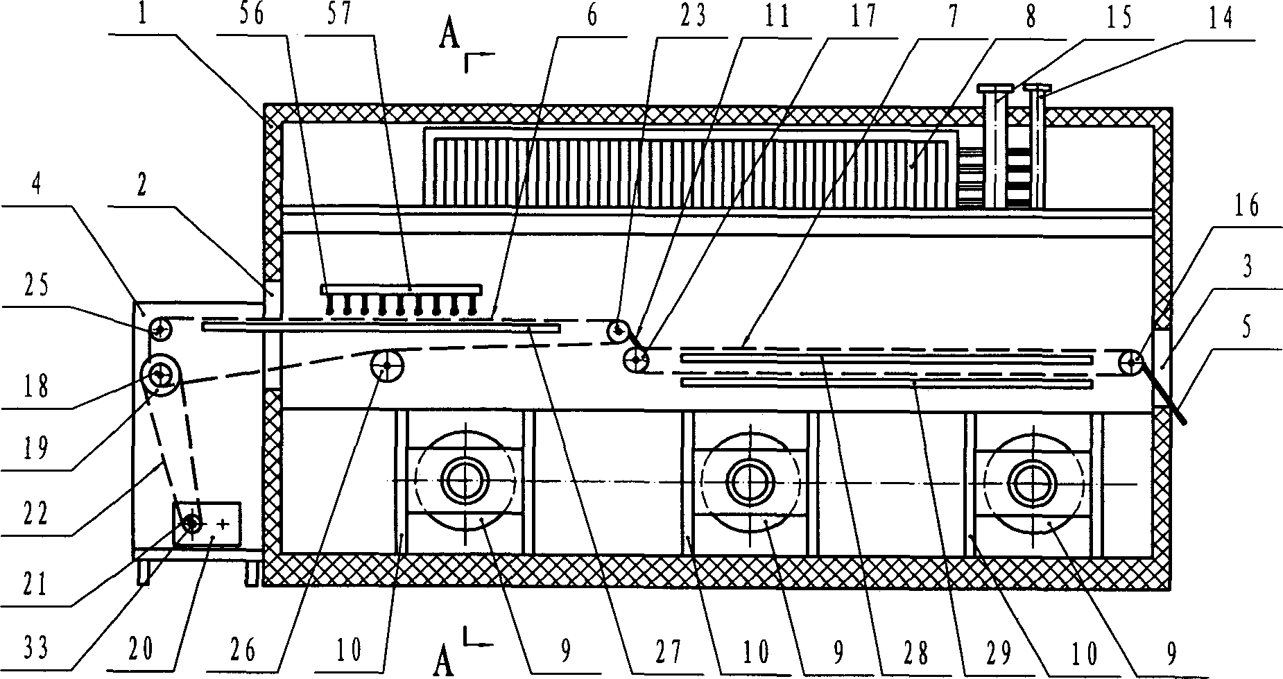
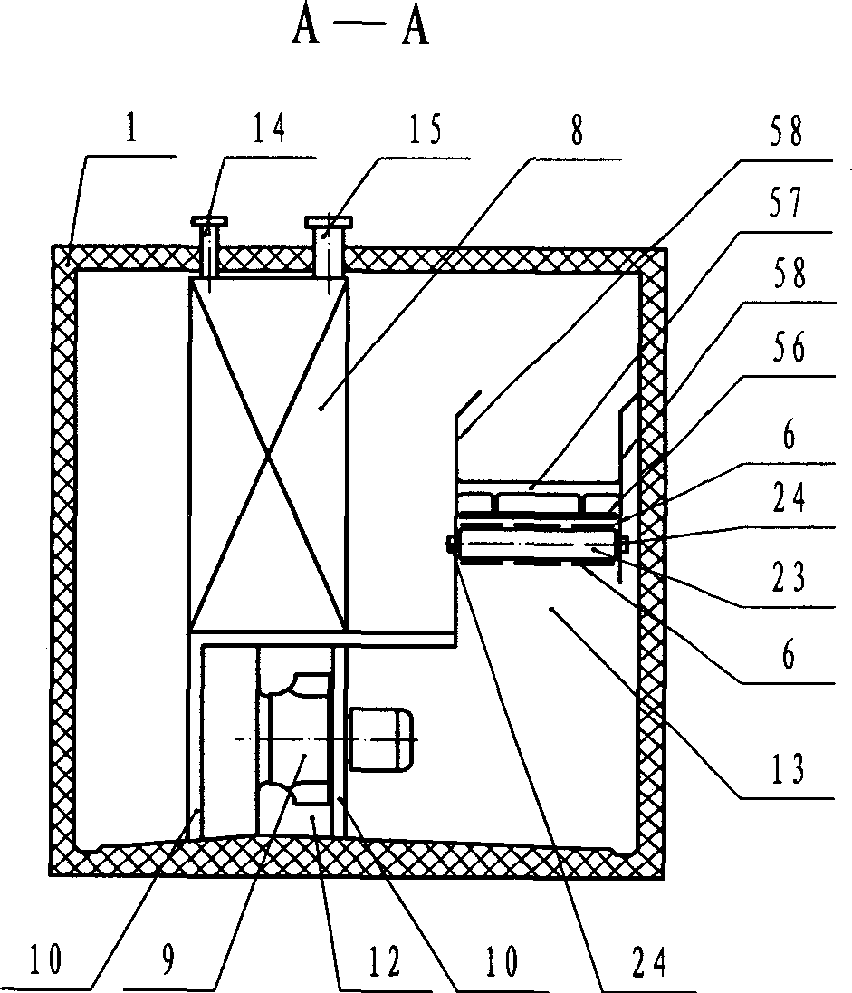
[0022] freezer (see figure 1 ) includes a thermal insulation box 1, a feed mechanism 4 and a discharge mechanism 5 respectively placed in the feed port 2 and the discharge port 3 of the thermal insulation box 1, and the first section of circulating conveying mesh belt installed in the thermal insulation box 1 6 and the second section of circulating conveying mesh belt 7, the cooling fan formed by the evaporator 8 and the fan unit 9 located in the heat insulation box 1, the bracket 10 connecting the evaporator 8 and the fan unit 9, and installed on the first section of circulating conveying mesh belt 6 and the scraper 11 between the second section of circulating conveying mesh belt 7. The air outlet 12 of the cooling fan communicates with the air collecting chamber 13 below the circulating conveying mesh belt (see figure 2 ), the liquid supply pipe 14 and the gas return pipe 15 of the evaporator are connected to the refrigeration unit respectively. The driving shaft roller 1...

Embodiment 2

[0025] The difference with Embodiment 1 is: the output shaft of the feed drive electric speed reducer 32 is fixedly equipped with a gear 48, and the gear 48 is meshed with the iron ring gear 36 for transmission (see Figure 6 ), drive the iron stopper 37 on the iron stop ring gear 36 to make forward low-speed rotary motion.

Embodiment 3

[0027] The difference with Embodiment 1 or 2 is: the output shaft 34 of the reciprocating vibration electric reducer 31 is fixedly connected with the output shaft 33 of the mechanically combined reciprocating vibration feeding device 20 with a shaft coupling 49 (see Figure 7 ), driving the output shaft 33 for reciprocating rotary motion, and 50 is a bearing for connecting the output shaft 33 with the frame 30.


PUM


Abstract

The present invention relates to a freezer unit. It includes a heat-insulating box body, feeding mechanism and discharge mechanism which are respectively placed in material inlet and material outlet of said heat-insulating box body, at least two circulation conveying mesh-belts mounted in the heat-insulating box body interior, evaporator positioned in heat-insulating box body interior and cold-air machine formed from fan group. The cold-air outlet of cold-air machine is communicated with air-collecting cavity positioned under the circulation conveying mesh-belt, the liquor supply tube of the evaporator and return tube are respectively connected with refrigerating machine group, first circulation conveying mesh-belt is driven by mechanical combined reciprocating vibration feeding device, and other circulation conveying mesh-belt is driven by electric speed-reducing machine. Said invention is high in freezing efficiency.

Description

Technical field: [0001] The invention relates to a freezing device, in particular to a mesh belt type freezing device. Background technique: [0002] In the freezing device of the multi-stage circulating mesh belt conveying frozen products, the first section of the circulating conveying mesh belt performs a low-speed feed motion of reciprocating vibration to prevent the frozen products on the mesh belt from producing frozen products and frozen products, frozen products and mesh belts. The adhesion between them is an advanced technology. However, the reciprocating vibration and feed of the existing circulating conveying mesh belt are driven by the servo motor system. Since the drive requires large vibration acceleration and large output torque, the assembly cost of the corresponding high-power, high-frequency response servo motor system High, not conducive to the popularization and application of the advanced technology of reciprocating vibration. Invention content: [00...

Claims


Application Information

Patent Timeline
IPC IPC(8): F25D13/06
Inventor 钱洪梁惠华楼晓华
Owner SIFANG TECH GRP CO LTD
Why Eureka
Try Eureka