Drive unit for generating an oscillatory motion for electrical small-scale units

A drive unit, oscillating motion technology, applied in the direction of electrical components, electromechanical devices, etc., can solve the problem of strong vibration of the motor shell and toothbrush, etc.

Active Publication Date: 2006-12-06
BRAUN AG
View PDF4 Cites 9 Cited by
  • Summary
  • Abstract
  • Description
  • Claims
  • Application Information

AI Technical Summary

Problems solved by technology

A further disadvantage is that the rotor always has a high mass or a high moment of i...

Method used


Image

  • Drive unit for generating an oscillatory motion for electrical small-scale units
  • Drive unit for generating an oscillatory motion for electrical small-scale units
  • Drive unit for generating an oscillatory motion for electrical small-scale units

Examples


Embodiment Construction

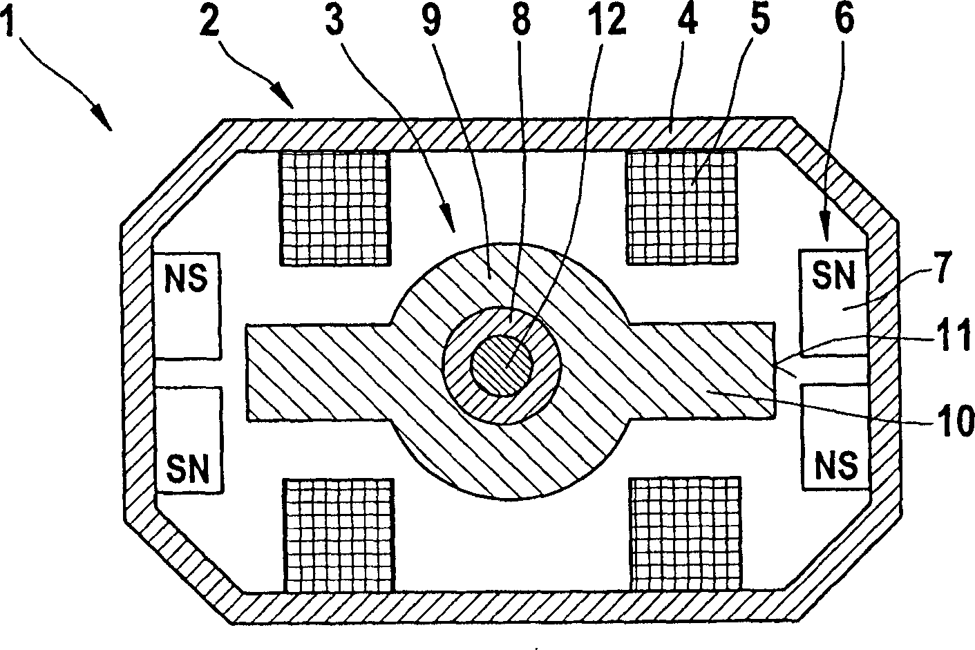
[0025] figure 1 An exemplary embodiment of a drive unit 1 constructed according to the invention is shown in a very schematic sectional view. As main functional components, the drive unit 1 comprises a stationary stator 2 and a rotor 3 arranged rotatably relative to the stator 2 about the longitudinal axis of the drive unit 1 . The stator 2 has a housing 4 made of a magnetizable material, two coils 5 connected in series, for example, and two magnetic devices 6 each having two permanent magnets 7 . Two coils 5 are arranged parallel to each other, wherein the axes of the two coils 5 coincide with each other and in figure 1 represents the mid-level distribution of . The magnetic devices 6 are arranged opposite each other on opposite sides of the housing 4 , wherein the individual permanent magnets 7 of the magnetic devices 6 are each positioned symmetrically with antiparallel polarity side by side with respect to the axis of the coil 5 . In this case, a small distance is alway...


PUM


Abstract

The invention relates to a drive unit (1) for generating an oscillatory motion for an electrical small-scale unit. The inventive drive unit (1) comprises a stator (2) containing at least one coil (5) and a first and second magnet arrangement (6) each having at least one permanent magnet (7). This drive unit (1) also comprises an armature (3) with a non-rotational symmetric design having a first and a second radial projection (10), which extend only over a partial area of the periphery of the armature (3) and are made of a magnetizable material. The inventive drive unit (1) is characterized in that by positioning the magnet arrangements (6) relative to the radial projections (10) of the armature (3), assignments between the magnet arrangements (6) and the radial projections (10) are formed in pairs in such a manner that the magnetic interaction between the magnet arrangement (6) and the radial projection (10) of one pair is permanently greater than the magnetic interaction between the magnet arrangement (6) and the radial projection (10) of two different pairs.

Description

technical field [0001] The invention relates to a drive unit for generating an oscillating motion for a small electrical appliance. Furthermore, the invention relates to a small electrical appliance with such a drive unit. Background technique [0002] Electric drive units for generating an oscillating movement are used, for example, in electric toothbrushes or electric shavers. For example from US 5,263,218 an electric toothbrush is known in particular with a pivotable lever arm, wherein the pivotable lever arm is arranged to oscillate by means of a fixed electromagnet and a fixed permanent magnet, on which the brush is arranged . The lever arm is therefore formed in a region adjacent to the electromagnet from a ferromagnetic material which partially surrounds the permanent magnet. The ferromagnetic material is used to couple the magnetic flux generated by the permanent magnet to the electromagnet and thus drive the lever arm. [0003] An oscillating tool, in particular...

Claims


Application Information

Patent Timeline
IPC IPC(8): H02K33/16H02K33/02H02K33/18
CPCH02K33/02H02K33/18H02K33/16
Inventor 伯恩哈德·克劳斯汉斯约尔格·赖克乌韦·舍贝尔
Owner BRAUN AG
Why Eureka
Try Eureka