DC motor drive device

A technology of DC motor and drive device, applied in the direction of reduction device of AC motor, starter of single DC motor, electric motor/converter plug, etc., can solve problems such as consumption of reactive power, reduce the minimum number of revolutions, improve Startup performance, cost reduction effect

Inactive Publication Date: 2006-12-06
ROHM CO LTD
View PDF1 Cites 14 Cited by
  • Summary
  • Abstract
  • Description
  • Claims
  • Application Information

AI Technical Summary

Problems solved by technology

[0007] However, in the method of Patent Document 1, although the magnitude of the starting current can be limited, since the current flows even when the motor is not rotating, reactive power is consumed
Furthermore, since a bias current to the degree of non-rotation flows, the range in which the number of rotations of the DC motor can be adjusted by adjusting the duty ratio of the PWM pulse is limited to that of the Figure 5 The scope of the same state of the art

Method used


Image

  • DC motor drive device
  • DC motor drive device
  • DC motor drive device

Examples


Embodiment Construction

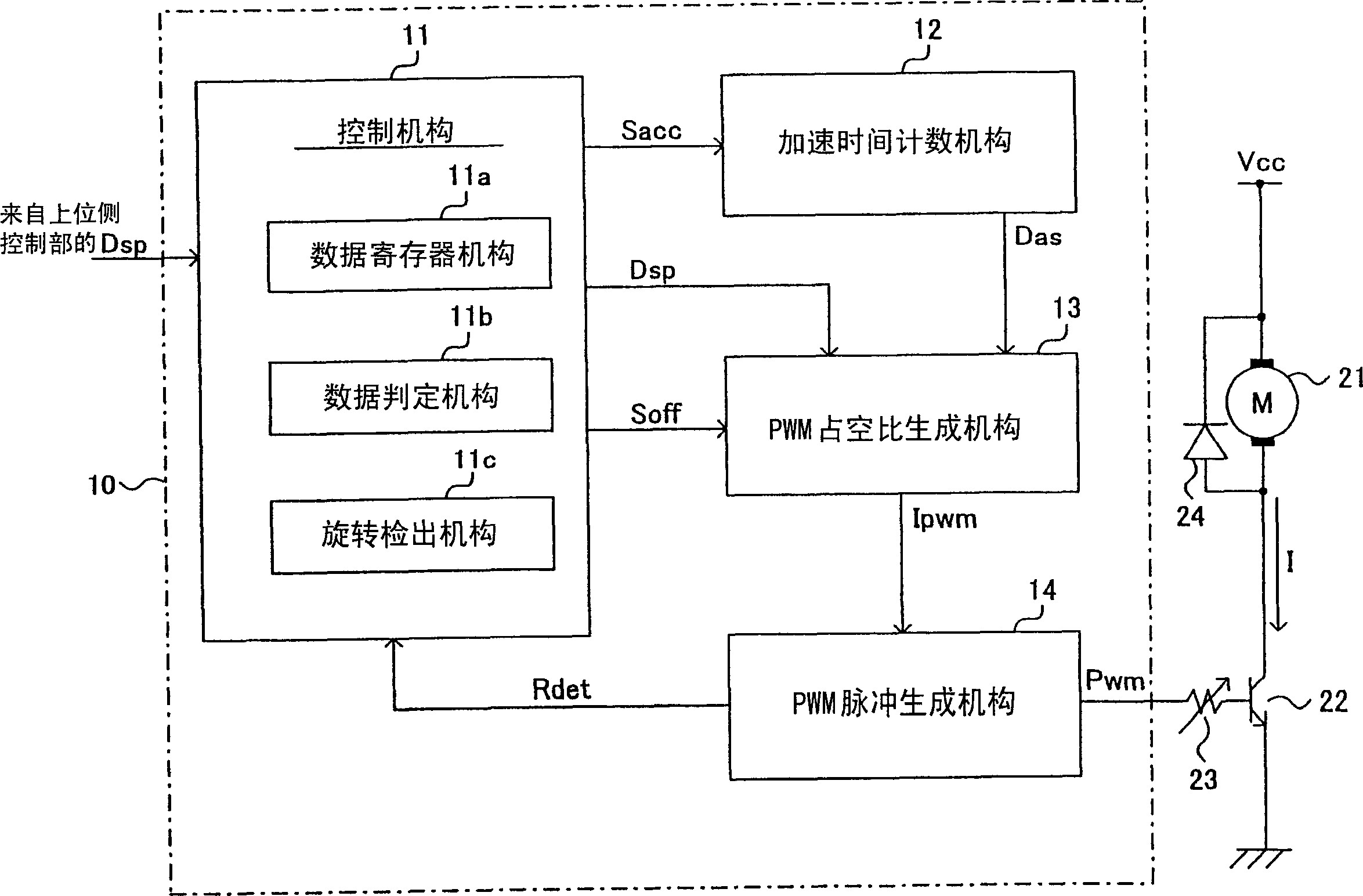
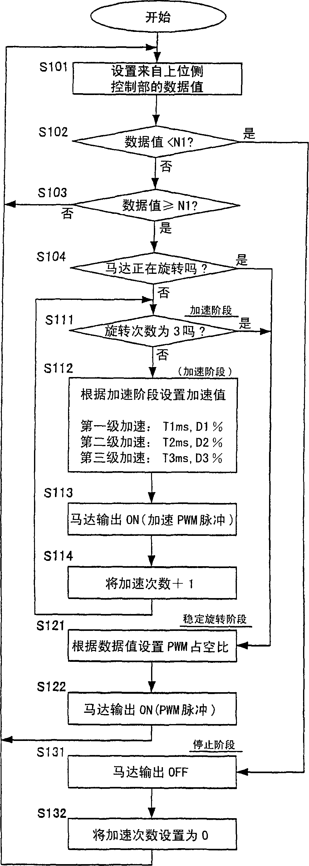
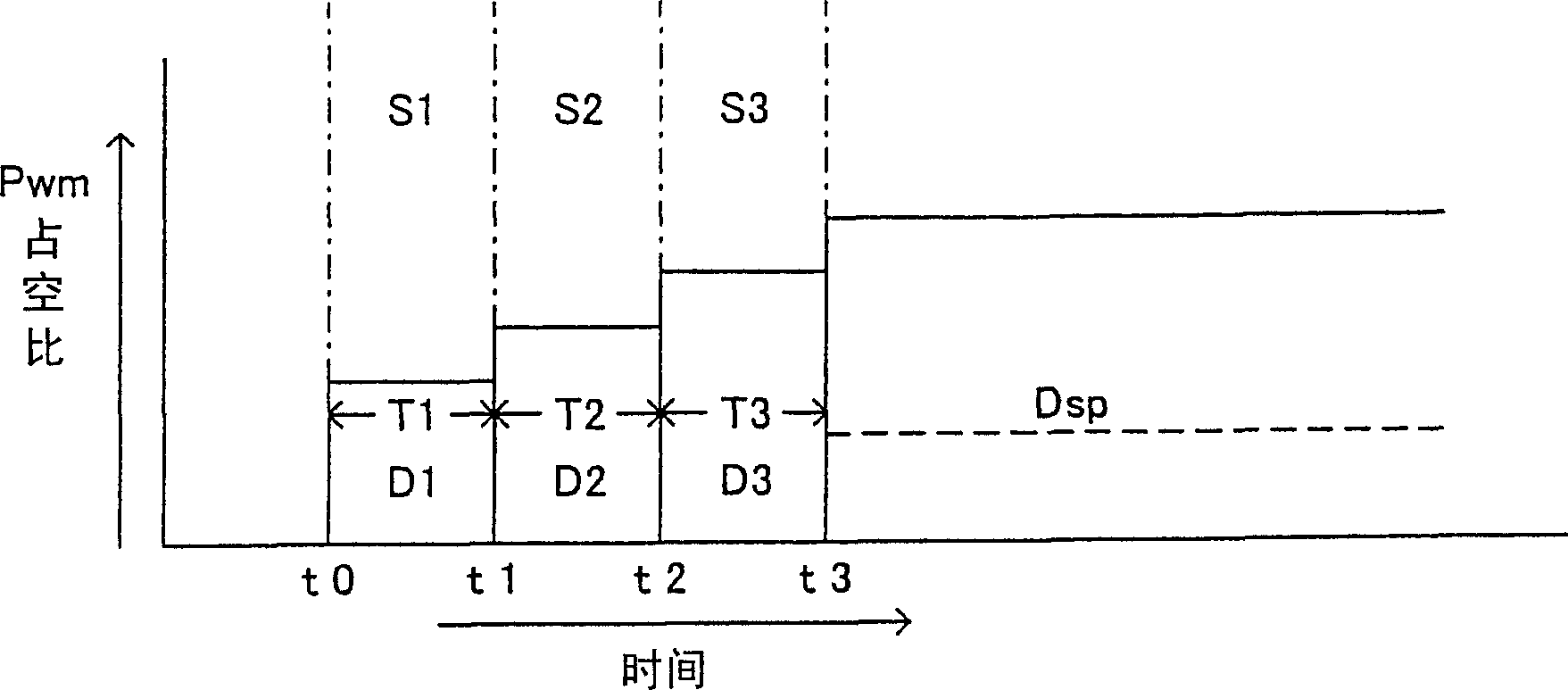
[0025] Next, embodiments of the DC motor driving device of the present invention will be described with reference to the drawings. figure 1 is a block diagram showing the configuration of a DC motor drive circuit according to an embodiment of the present invention. figure 2 is description figure 1 flow chart of the action. Figure 3 is a representation of figure 1 , figure 2 A schematic diagram of an example of the operating state of the DC motor drive circuit.

[0026] exist figure 1 In , the DC motor drive is controlled by an open-loop control method. The DC motor 21 and the switching transistor 22 are connected between a power supply voltage Vcc and ground. By supplying a PWM pulse Pwm from the motor drive control circuit 10 to the base of the switching transistor 22, the switching transistor 22 is controlled to be turned on or off according to the PWM pulse Pwm. The adjustment resistor 23 is a variable resistor used to adjust the base current of the transistor ...


PUM


Abstract

There is provided a DC motor drive device of the open loop control method. It is judged whether speed instruction data supplied corresponds to the DC motor drive instruction according to the speed instruction data. When it is decided that the speed instruction data is a drive instruction, switch means is controlled by a PWM pulse of a predetermined duty ratio during a predetermined acceleration period, thereby accelerating the DC motor. When the acceleration period has terminated, the switch means is controlled by a PWM pulse of the duty ratio in accordance with the speed instruction data, there by driving the DC motor. This limits the start current when performing start so as to reduce withstand current of a switching transistor or the like and surely performs start so as to increase the motor speed control range.

Description

technical field [0001] The present invention relates to a DC motor driving device capable of reliably starting and suppressing a starting current in a DC motor driving device that rotates a DC motor at a speed corresponding to a speed command from the outside. Background technique [0002] In game machine controllers or toys, etc., motors are used for driving or vibrating. Because this kind of motor uses a battery as a power source, is cheap, and its driving circuit is relatively simple, etc., a DC motor is mostly used. [0003] Figure 5 It is a schematic diagram showing a DC motor drive circuit based on an open-loop control method generally used in the prior art. Such as Figure 5 As shown, a DC motor 1 is connected between a power supply voltage Vcc and ground through a switching transistor 2 that performs on / off switching. Since the speed of the DC motor 1 is proportional to the current I flowing thereon, the transistor 2 is controlled by a PWM (pulse width modulation)...

Claims


Application Information

Patent Timeline
Patent Type & Authority Applications(China)
IPC IPC(8): H02P1/18H02P7/29
CPCH02P7/29H02P1/18
Inventor 斋藤孝一佐藤友威
Owner ROHM CO LTD
Why Eureka
Try Eureka