Carbide alloy metal saw production process

A technology of saw blade milling cutter and hard alloy, which is applied in the direction of milling cutter, metal processing equipment, milling machine equipment, etc., can solve the problem of no production method of saw blade milling cutter, etc., and achieve the effect of convenient use

Inactive Publication Date: 2006-12-13
周荣根
View PDF0 Cites 13 Cited by
  • Summary
  • Abstract
  • Description
  • Claims
  • Application Information

AI Technical Summary

Problems solved by technology

At present, there is no saw blade milling cutter for milling knitting needle grooves on the market, and there is no production method for this type of saw blade milling cutter

Method used


Image

  • Carbide alloy metal saw production process

Examples


Embodiment Construction

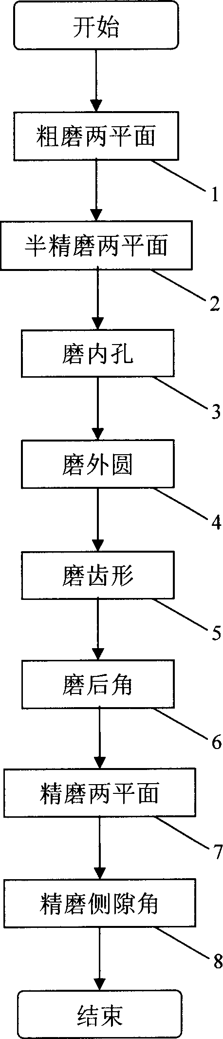
[0022] figure 1 It is a flowchart of the manufacturing process of the cemented carbide saw blade milling cutter of the present invention. Include the following steps in turn:

[0023] Rough grinding of two planes 1: Use a universal tool grinder and a bowl-shaped grinding wheel with a grain size of about 120 to roughly grind the two planes of the workpiece, and grind the thickness of the workpiece to 0.40mm-0.42mm; the thickness of the workpiece is preferably ground to 0.42mm; requirements The runout at the outer edges of the two planes is not more than 0.01mm, and the moving speed of the workpiece is between 10-12m / min.

[0024] Semi-finishing two planes 2: using a cylindrical grinder and a parallel grinding wheel with a grain size of about 100 to semi-finish the two planes of the workpiece, and grind the thickness of the workpiece to 0.26mm-0.28mm; the thickness of the workpiece is preferably ground to 0.28mm; It is required that the runout at the outer edges of the two pla...


PUM


Abstract

The invention discloses a process for preparing hard alloy saw blade milling cutter, comprising following steps: coarse grinding two surface, semi-correct grinding two surface, grinding internal hole, grinding external circle, grinding gear form, grinding bottom rake and correct grinding two surface and correct grinding side clearance angle. The invention employs several times grinding to prepare ultra-fine particular hard alloy saw blade milling cutter, the thickness of blade milling cutter is very thin, side clearance angle 0degree8'-0degree12'is milled on work piece for further convenience of milling cutter.

Description

【Technical field】 [0001] The invention relates to a cemented carbide saw blade milling cutter, in particular to a manufacturing process of a cemented carbide saw blade milling cutter. 【Background technique】 [0002] The overall progress of manufacturing technology has pushed the cutting technology to a new stage of high-speed cutting. As a new cutting process, high-speed cutting has shown unique advantages. First of all, the cutting efficiency is doubled; secondly, high-speed cutting is conducive to improving product quality, reducing manufacturing costs, and shortening lead times. In addition, on the basis of high-speed cutting technology, new technologies such as dry cutting (quasi-dry cutting, minimal lubrication cutting) and hard cutting (replacing grinding with turning, replacing grinding with milling) have been developed, which not only improves the processing efficiency, but also changes the traditional It is the boundary between different cutting processes in the se...

Claims


Application Information

Patent Timeline
Patent Type & Authority Applications(China)
IPC IPC(8): B24B3/04
Inventor 周荣根
Owner 周荣根
Why Eureka
Try Eureka